APhO 2001, Експеримент — Задача 1. Question (1)
2nd Asian Physics Olympiad — TAIPEI, TAIWAN — Experimental Competition — Thursday, April 26, 2001 · 26 април 2001 г. · 3 т.
Read This First
Time Available : 5 hours
Read This First:
- Use only the pen provided.
- Use only the front side of the answer sheets and paper.
- In your answers please use as little text as possible ; express yourself primarily in equations, numbers and figures. If the required result is a numerical number, underline your final result with a wavy line.
- Write on the blank sheets of paper the results of all your measurements and whatever else you consider is required for the solution of the question and that you wish to be marked.
- It is absolutely essential that you enter in the boxes at the top of each sheet of paper used your Country and your student number (Student No.). In addition, on the blank sheets of paper used for each question, you should enter the number of the question (Question No.), the Section label, the progressive number of each sheet (Page No.) and the total number of blank sheets that you have used and wish to be marked for each question (Total No. of pages). If you use some blank sheets of paper for notes that you do not wish to be marked, put a large cross through the whole sheet and do not include them in your numbering.
- At the end of the exam please put your answer sheets and graphs in order.
Условие
Basic Characteristics of Solar Cells
I. Background description
The purpose of this experiment is to explore the basic characteristics of solar cells. Solar cells can absorb electromagnetic waves and convert the absorbed photon energy into electrical energy. A solar cell mainly consists of a diode, whose forward dark current-voltage relationship (i.e., I-V curve under no light illumination) can be expressed as
where and are constants.
The diode is made up of a semiconductor with a band gap of (see Fig. 1). When the energy of the incident photon is larger than the band gap, the photon can be absorbed by the semiconductor to create an electron-hole pair. The electrons and holes are then driven by the internal electric field in the diode to produce a photocurrent (light-generated current). There are several important parameters other than light-generated current involved in a solar cell.
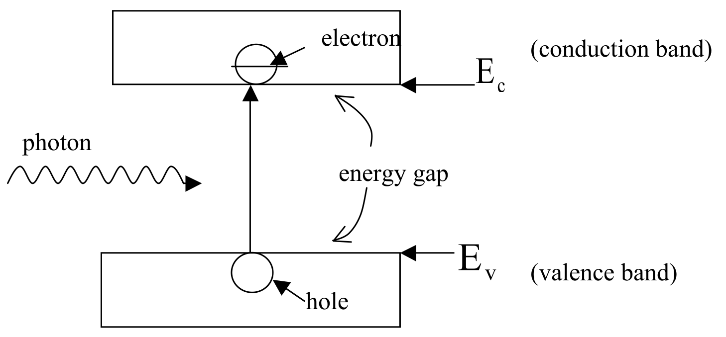
Brief explanations of the terminologies and basic principles are listed below:
(1) Short-circuit current () is the output current of the solar cell when the external circuit is shorted, i.e., zero load resistance.
(2) Open-circuit voltage () is the output voltage of the solar cell when the external circuit is open, i.e., infinite load resistance. is also referred to as photovoltaic voltage.
(3) is the maximum output power of the solar cell, i.e., the maximum value of .
(4) The filling factor (FF) is defined to be , which represents an important parameter used to evaluate the quality of the solar cell.
(5) Because the photocurrent is produced by photon absorption by the semiconductor, the spectral response of the photocurrent can be used to determine the semiconductor band gap. From the band gap value, one can infer the particular semiconductor material used.
(6) Any incident photon with photon energy larger than the semiconductor band gap can contribute to the photocurrent () of the solar cell, thus
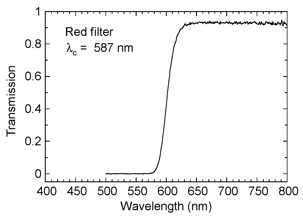
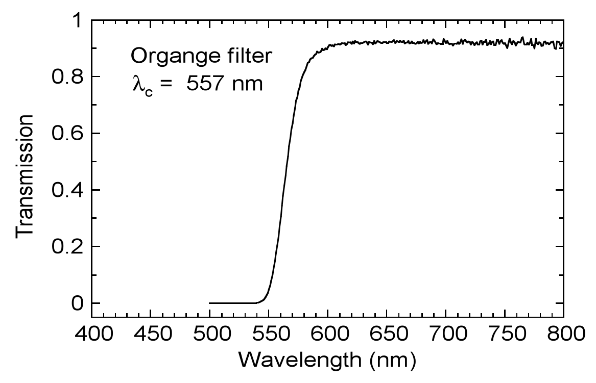
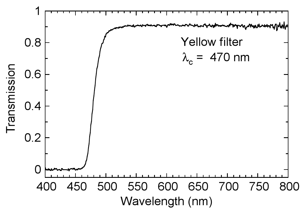
where is the number of electrons per unit wavelength produced by photons with wavelength , is the cut-off wavelength of the optical filter (see Fig. 2, Fig. 3, and Fig. 4), and is the longest wavelength capable of producing a photocurrent. Here is approximately constant in the visible spectral range, and each optical filter provided in this experiment cuts off all light with wavelengths shorter than a certain cut-off wavelength . Therefore, the spectral response of with an optical filter can be simplified to be
(7) The photon energy E is related to the photon wavelength as ; the unit for is nm () and the unit for E is eV (electron-volt) in this equation.
II. Equipments and materials
(1) A solar cell in a black box with pre-installed electrical connections
(2) Two digital electrical multimeters
(3) A set of dry cell batteries (1.5 V × 2)
(4) One precision variable resistor (0-5 kΩ)
(Caution: Do not connect the central connecting lead (the red wire) of the variable resistor directly to the battery, it may damage the resistor.)
(5) A white light source with power supply
(6) Two polarizers (Note: these polarizers are less effective for light with wavelengths shorter than that of yellow light,that is the cut-off wavelength of the yellow filter.)
(7) Red, orange, and yellow optical filters, one of each (their spectral specifications are shown in Fig. 2, Fig. 3, and Fig. 4)
(8) An optical mount for the optical filters or polarizers (Note: optical filters and polarizers can be mounted together on the same optical mount.)
(9) One optical bench
(10) Wire joining devices: 6 small springs
(11) One 45 cm ruler
(12) Regular graph paper (10 sheets), semi-log graph paper (5 sheets)
(13) Two light-shielding boards
(Note: To avoid deterioration due to heat, polarizers and filters should be set at a distance as far away from the light source as possible.)
III. Experimental steps
Measure the dark I-V characteristic of the forward biased solar cell.
a. Draw a diagram of the electrical circuit you used.
b. Plot the I-V curve and determine the values of and using the I-V data you obtained..
Отговори
b. β = 3.0 ~ 8.0 V⁻¹; I0 = 1.3×10⁻¹¹ ~ 2.1×10⁻⁹ A (1.3×10⁻⁸ ~ 2.1×10⁻⁶ mA)
Accepted ranges from the official marking scheme; the sample graph gives I0 = 1.5 × 10⁻⁷ mA, β = 6.5 (1/V).
Решение
(1) (Question (1) : 3 points)
Measure the dark I-V characteristic of the forward biased solar cell .
a. Draw a diagram of the electrical circuit you used.
b. Determine the values of and .
a. Circuit diagram
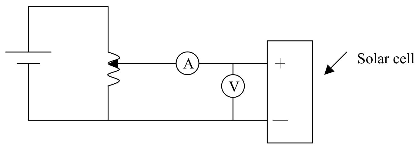
⊙Correct Circuit diagram (1 point)
b. Determine the values and in the equation of dark current-voltage characteristic.
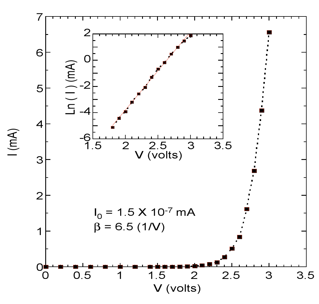
| 1 | ××× | |
| 2 | ||
| 3 |
⊙Correct I-V curve (1 point)
- Proper data table marked with variables and units (0.2 points)
- Properly choose the size of scales and units for abscissa and ordinate that bear relation to the accuracy and range of the experiment (0.3 points)
- Correct curve including correctly transform the I-V curve into linear curve (0.5 points)
⊙Correct value of expressed in significant figures and with error ()
() (0.5 points)
⊙Correct value of expressed in significant figures and with error ()
() or
() (0.5 points)
(for A)
(for mA)
Оригинал в Архива: exp.pdf · официални решения: exp_sol.pdf