APhO 2003, Експеримент — Задача 2. II. Cylindrical Bore
4th Asian Physics Olympiad — Experimental Competition — 25 April 2003 · 25 април 2003 г. · 10 т.
Условие
Background
There are many techniques to study the object with a bore inside. Mechanical oscillation method is one of the non-destructive techniques. In this problem, you are given a brass cube of uniform density with cylindrical bore inside. You are required to perform non-destructive mechanical measurements and use these data to plot the appropriate graph to find the ratio of the radius of the bore to the side of the cube.
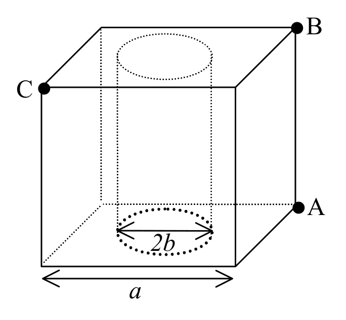
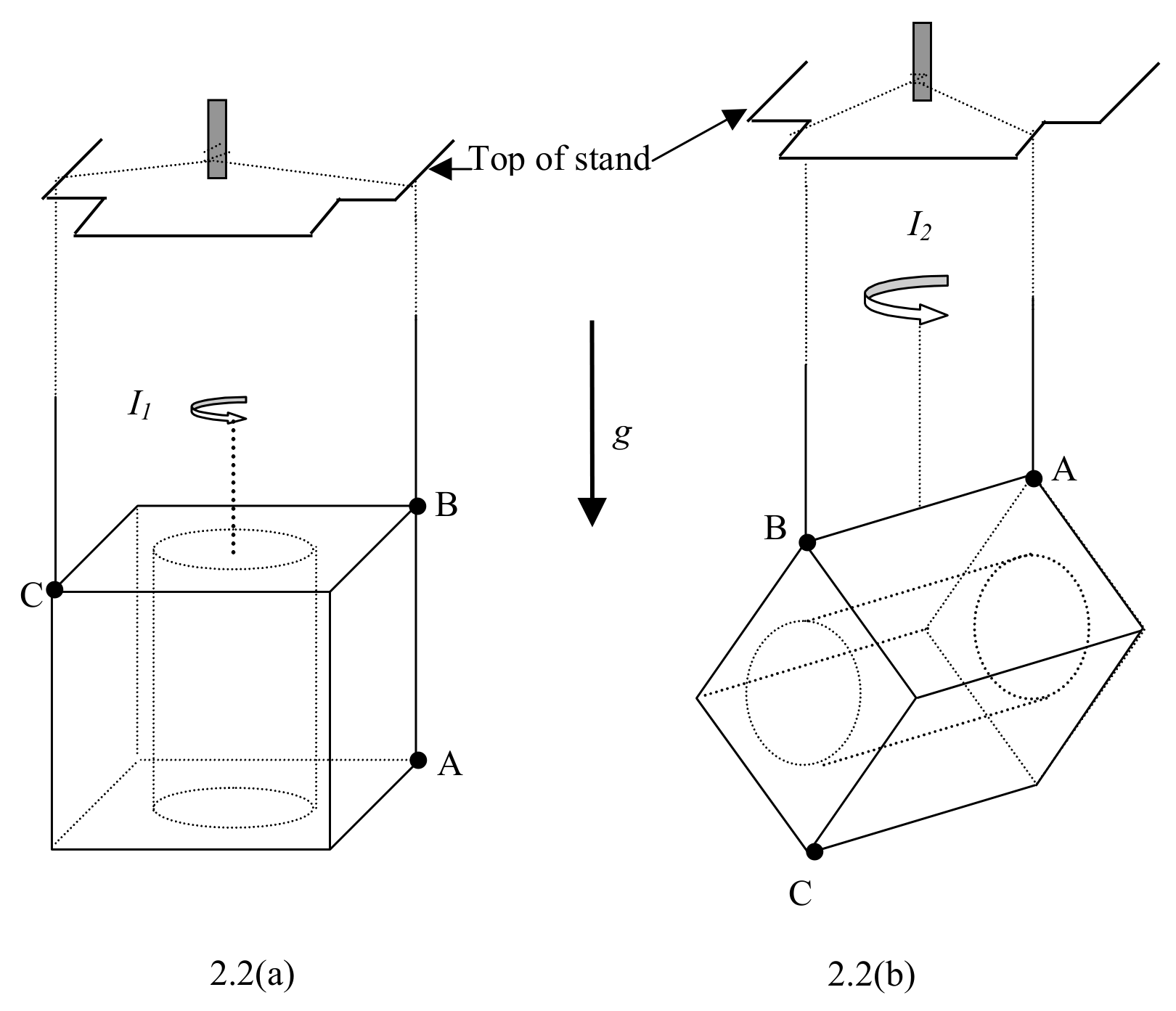
The cube of sides has a cylindrical bore of radius along the axis of symmetry as shown in Fig. 2.1. This bore is covered by very thin discs of the same material. A, B and C represent small holes at the corners of the cube. These holes can be used for suspending the cube in two configurations. Fig. 2.2(a) shows the suspension using B and C; the other suspension is by using A and B as shown in Fig 2.2(b).
Students may use the following in their derivation of necessary formulae:
For a solid cube of side
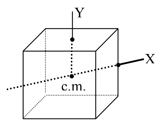
c.m. = centre of mass
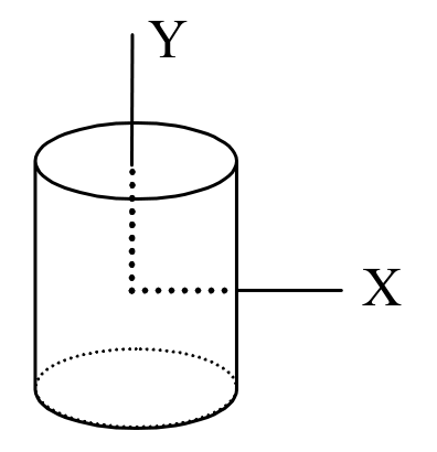
For a solid cylinder of radius length
Materials and apparatus
- brass cube
- stop watch
- stand
- thread
- ruler/ centimeter stick
- linear graph papers
Experiment
a) Choose only one of the two bifilar suspensions as shown in Fig. 2.2, and derive the expressions for the moment of inertia and the period of oscillation about the vertical axis through the centre of mass in terms of and where is the length of each thread and is the separation between threads. (2 points)
b) Perform necessary non-destructive mechanical measurements and use these data to plot an appropriate graph and then find the value of . (8 points)
The value of for Bangkok = .
Отговори
a)
Configuration Fig. 2.2(a) gives T1, configuration Fig. 2.2(b) gives T2.
b) 0.24
Official sample data: x = b/a = 0.24 ± 0.02 for configuration Fig. 2.2(a) and 0.25 ± 0.03 for configuration Fig. 2.2(b).
Решение
Solution and Marking Scheme
Experiment
II. Cylindrical Bore
a) Derivation of moment of inertia (0.5 points)
Configuration Fig. 1.2(a)
Configuration Fig. 1.2(b)
Derivation of period of oscillation
For both configurations:
the restoring torque
where and
net mass where
since (0.5 points)
For configuration in Fig. 2.2(a),
For configuration in Fig. 2.2(b),
b) For configuration in Fig. 2.2(a),
| (cm) | for 40 oscillations(s) | (s) | (s) | ||
|---|---|---|---|---|---|
| 16.5 | 20.60 | 20.50 | 20.70 | 0.515 | 0.265 |
| 17.9 | 21.35 | 21.35 | 21.30 | 0.533 | 0.284 |
| 22.6 | 24.05 | 24.00 | 24.00 | 0.601 | 0.362 |
| 27.4 | 26.55 | 26.45 | 26.55 | 0.663 | 0.440 |
| 29.0 | 27.40 | 27.40 | 27.40 | 0.685 | 0.469 |
| 34.2 | 29.75 | 29.70 | 29.65 | 0.743 | 0.551 |
| 36.1 | 30.60 | 30.60 | 30.50 | 0.764 | 0.584 |
| 43.0 | 33.40 | 33.35 | 33.50 | 0.835 | 0.698 |
(3 points):
3 sets of oscillations (1 point) [2 sets –0.3, 1 set –0.7]
(1 point) [, -0.3, , -0.7, , -1.0]
number of lengths, , (1 point) [4, -0.3, 3, -0.5, 1 or 2, -1.0]
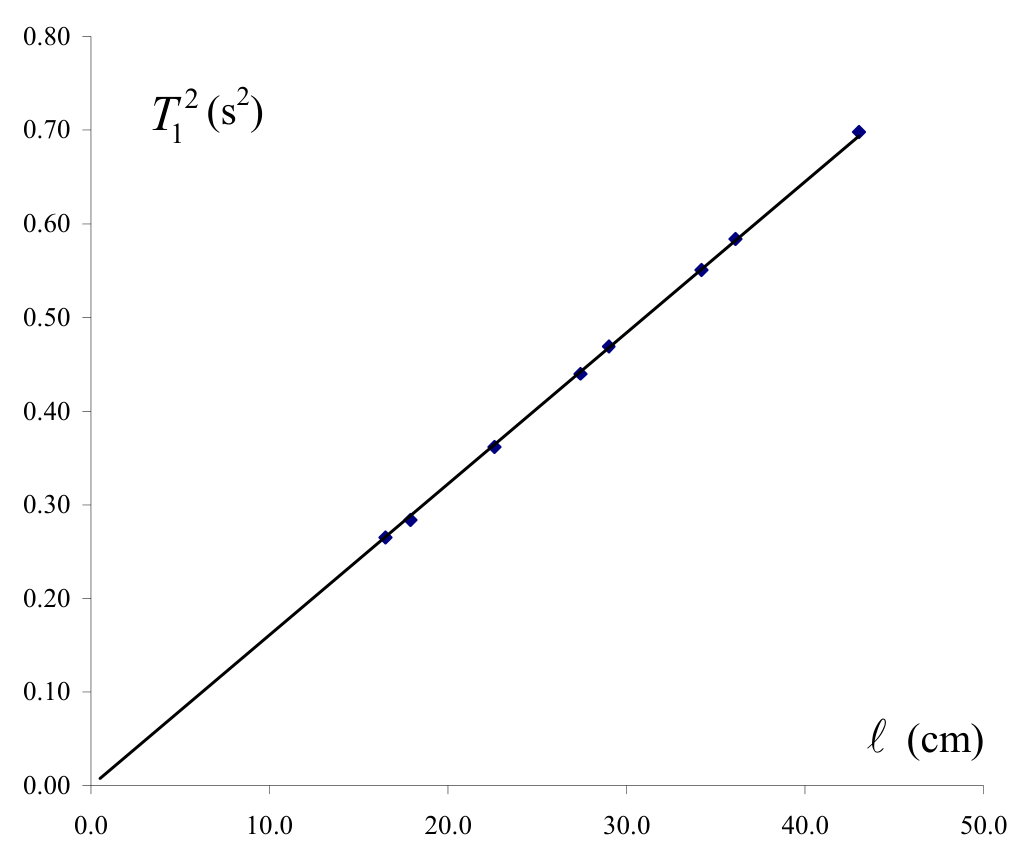
slope of graph:
For configuration in Fig. 2.2(b),
| (cm) | for 40 oscillations (s) | (s) | (s) | ||
|---|---|---|---|---|---|
| 43.8 | 46.95 | 46.90 | 46.80 | 1.172 | 1.374 |
| 36.0 | 42.70 | 42.45 | 42.50 | 1.064 | 1.132 |
| 30.9 | 39.60 | 39.40 | 39.35 | 0.986 | 0.973 |
| 26.5 | 36.40 | 36.30 | 36.45 | 0.909 | 0.827 |
| 19.5 | 30.80 | 30.85 | 30.75 | 0.776 | 0.593 |
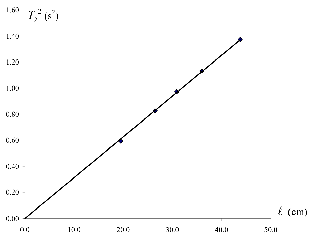
slope of graph:
graph (3.0 points):
- good graph (1.5 points)
- slope (1.0 point)
- error of experimental points (0.5 point)
calculation for (1.0 point) error estimation (1.0 point)
Оригинал в Архива: exp2.pdf · официални решения: exp2_sol.pdf