APhO 2018, Теория — Задача 3. Thermoelectric effects and their applications in thermoelectric generator and refrigerator
Theory Q3 — 19th APhO Asian Physics Olympiad, Hanoi - Viet Nam 2018 — English (Official) · 10 т.
Условие
Introduction: Thermoelectric effects
Thermoelectric effects in conducting materials are due to the interplay between heat current and electrical current. In this problem we consider only three predominant thermoelectric effects, namely the Joule, the Seebeck and the Peltier effects, neglecting the others.
The Joule effect is a consequence of the interaction between electrical carriers and crystal lattice. Moving directionally in presence of electrical current, carriers transfer a part of their energy to the vibrating crystal lattice, and as a result the crystal is heated. The Joule effect is irreversible.
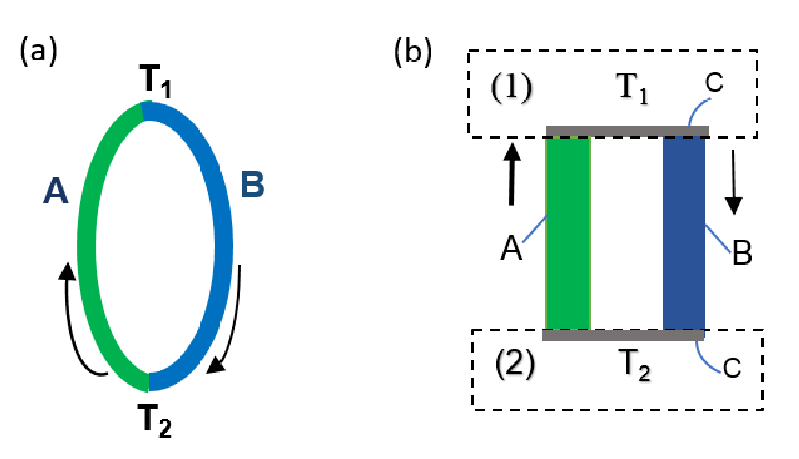
The Seebeck effect can be observed in a thermocouple consisting of two dissimilar conducting bars A and B connecting by direct junction (Fig. 1a) or junction via an intermediate material C (Fig. 1b). The material C is good electrical conductor with very small specific heat. When the two junctions of the thermocouple are maintained at different temperatures and (Fig. 1a,b) the Seebeck electromotive force (emf) is produced
where is the Seebeck coefficient of the thermocouple. is considered temperature independent .
The Seebeck effect is applied in thermoelectric generator to convert heat energy into electrical one.
The Peltier effect
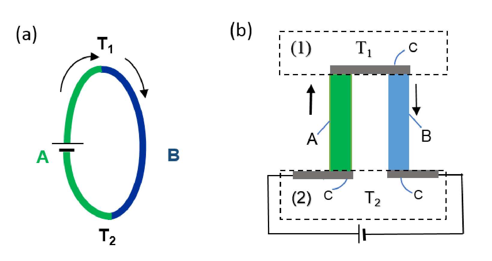
Whenever current passes through a thermocouple circuit consisted of two dissimilar conductors A and B with direct junctions (Fig. 2a) or junctioned via intermediate conductor C (Fig. 2b), depending on the current direction, heat is either absorbed or released at the junctions of the two conductors. This is the Peltier effect. The Peltier heat power q appeared at a junction is
is the Peltier coefficient of this junction. The Seebeck and Peltier effects are reversible effects in contrast to the irreversible Joule effect. Although the Seebeck and Peltier effects need junctions between the thermoelements, they are essentially bulk effects. A closed electrical cycle in a thermocouple with the Peltier effect (Fig. 2b) can be used as a refrigerator when heat is removed from one isolated junction and rejected at the other.
For simplicity, the heat radiation, circulation, conduction through surrounding environment are considered negligible, and heat current is supposed to be inside the thermocouple and at the heat source and the heat sink.
Data for thermal and electrical properties of materials and the thermocouple studied in this problem are given in the Table 1 and 2 for numerical calculation.
| Name | Material | Resistivity () | Thermal conductivity () |
|---|---|---|---|
| A | 1.4 | ||
| B | 1.4 |
Table 1: Parameters of materials used in thermocouple (at room temperature)
| Thermocouple AB | Length (m) | Seebeck's coefficient |
|---|---|---|
| 0.02 | 420 |
Table 2: Parameters of the thermocouple.
A. Heat transfer and thermoelectric generator
A1. Heat transfer in a homogeneous conducting bar
An electric current (Figure 3) flows along a homogeneous conducting bar with length , resistivity , thermal conductivity k. The two ends of the bar are located at coordinates and in the OX axis. The temperature at is , at is , both temperatures are kept constant.
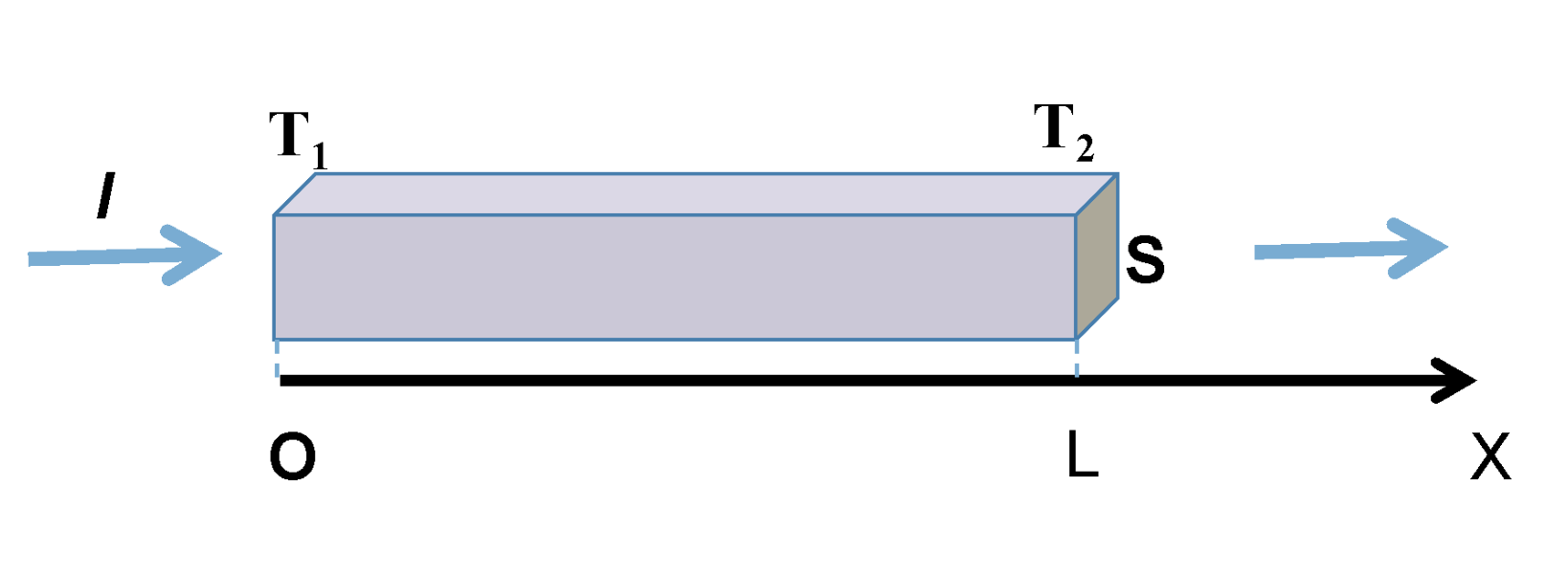
The heat current (the amount of heat transferred via perpendicular cross-section per unit time) flowing in the bar is described by the Fourier law
here is thermal conductivity, and is the cross-sectional area of the bar.
A1.1 Find the temperature distribution when varies along the bar at the steady state assuming no heat loss to the surroundings.
Hint: the equation has the solution , where and are derived from boundary conditions. [0,75 т.]
A1.2 Find the heat current at point and , at the two ends, respectively. [1 т.]
A2. Relation between Peltier and Seebeck Coefficients
Relation between Peltier and Seebeck coefficients for all temperature range is generally proved in thermodynamics. Here, this relation is derived for the particular case when the thermocouple is made of conducting materials A and B (Fig.1b) with the Seebeck coefficient and small-enough resistivity so that the Joule effect can be neglected. The Peltier coefficients at the hot (temperature ) and cold ( temperature ) junctions are and correspondingly. During electrical process, the electron gas in the thermocouple performs a ideal thermodynamic cycle.
A2.1 Find the expression for the heat current received by the electron gas from the heat source with temperature . [0,25 т.]
A2.2 Find the expression for the heat current transferred by the electron gas to the heat sink with temperature . [0,25 т.]
A2.3 Find the net electrical power produced by the electron gas if the Seebeck coefficient is . [0,5 т.]
A2.4 Express the Peltier coefficient at a junction in term of the Seebeck coefficient and the temperature of the junction. [0,5 т.]
A3. Thermoelectric generator
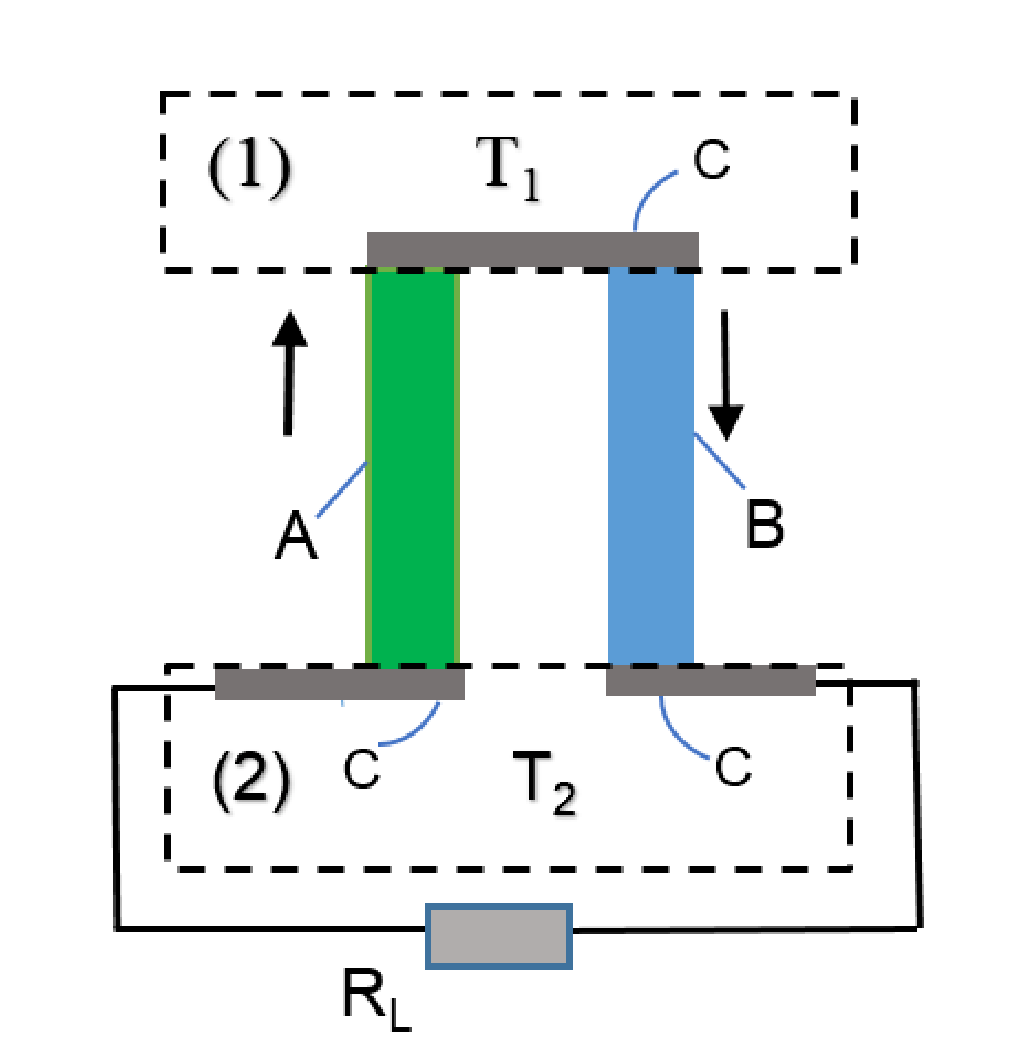
Hereafter the Peltier coefficient is taken to be equal to for all temperatures and the Joule heat must be included in consideration.
The thermocouple consisting of two conducting bar A and B with equal length is used as thermoelectric generator (Fig. 4). The parameters of the bars A and B are: cross-sectional areas , ; resistivities ; thermal conductivities . The lower ends of the A and B bars are connected to a load of resistance . Parameters of the thermocouple are: the Seebeck coefficient, the internal resistance, the thermal conductance. The upper hot end (lower cold end) of the thermocouple is maintained at temperature and . Denote as the heat power taken from the heat source with temperature , as the heat power transferred to the heat sink with temperature by the thermocouple.
A3.1 Find the expressions for in terms of the thermocouple parameters the temperatures and the current [0,5 т.]
The efficiency of the thermoelectric generator is defined as , where the electrical power of the load. The ratio between the load and internal resistances of the thermocouple is denoted as
A3.2 Find the expression for the efficiency in terms of the thermocouple parameters the temperatures and the resistance ratio [0,75 т.]
In order to determine the efficiency of thermoelectric generators, the following properties of the thermocouple are needed: low electrical resistance to minimize Joule heating, low thermal conductivity to retain heat at the junctions, and a maintained large temperature gradient. These three properties are put together in one quantity , which is called the figure-of-merit of the thermocouple.
A3.3 Find the expression for the efficiency in terms of , the ideal Carnot cycle efficiency , and . [0,25 т.]
A4. The maximum efficiency
The efficiency of the thermocouple equals when the electric power of the load takes the maximum value, .
A4.1 Find the expression for the in terms of the figure of merit and . [0,25 т.]
The efficiency is maximum when the resistance ratio m takes some value which is denoted by.
A4.2 Find the expression for in terms of and . [0,75 т.]
A4.3 Express the maximum efficiency via and . [0,25 т.]
A5. The maximum figure of merit
Increasing the figure of merit of the thermocouple leads to the increase of the efficiency of the thermoelectric generator. In practice, the cross-sectional areas of the bars of the thermocouple are chosen so that the figure of merit of the thermocouple has maximum value
A5.1 Derive the expression for the ratio between the cross-sectional areas of the bars in terms of when the figure of merit of the thermocouple is maximum. [0,5 т.]
A5.2 Express the maximum figure of merit in term of , [0,25 т.]
A6. The optimum efficiency
The optimum efficiency of the thermoelectric generator is defined as the efficiency when the electric power at the load and the figure of merit both are at the maximum values. The hot heat source and cold heat sink are maintained at temperatures respectively.
A6.1 Find the numerical value of the thermoelectric generator made from materials with parameters given in Table 1 and compare it with the ideal efficiency . [0,5 т.]
A6.2 Find the numerical value of the maximum efficiency of the thermoelectric generator made from given materials. [0,25 т.]
B. Thermoelectric refrigerator
The thermocouple with parameters given in the question A3 is used as a thermoelectric refrigerator and described in the Fig.5.
B1. The cooling power and the maximum temperature difference
The upper end of the thermocouple is a heat source with the initial temperature . It is thermally isolated with ambient environment, and needs to be cooled. The lower ends of the thermocouple, A and B bars are connected to a battery and are at the temperature of the heat sink. The sense of the electrical current is chosen so that the Peltier heat is absorbed at the upper junction and released to the heat sink at the lower junction.
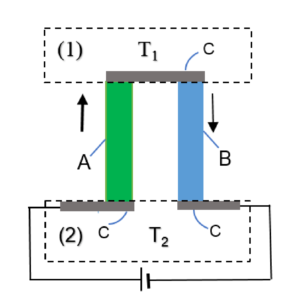
B1.1 Find the expression for the cooling power (heat current flows from the heat source to the bars of the thermocouples) in terms of the thermocouple parameters and . [0,25 т.]
B1.2 Find the expression for the maximum temperature difference in term of the figure of merit Z of the thermocouple and the lowest temperature of the isolated heat source . [0,5 т.]
B2. The working current
The thermocouple made from materials A and B with best value of figure of merit found in part A is used for the refrigerator.
B2.1 Calculate the numerical value of the minimum temperature of the isolated heat source if the temperature of the heat sink is . [0,25 т.]
B2.2 Calculate the working current intensity of the thermoelectric refrigerator when the temperature of the heat source is at the minimum value and the temperature of the heat sink . For simplicity the cross-sectional areas of the bars are taken to be equal, . [0,5 т.]
B3. The coefficient of performance
When the temperature difference is less than its maximum value , the coefficient of performance is usually used for assessing of the performance of the thermoelectric refrigerator. , where is the supplied electrical power.
B3.1 Find the expression for the coefficient of performance in terms of the parameters of the thermocouple and . [0,5 т.]
When the coefficient of performance has its maximum value , the current intensity is .
B3.2 Find the expression for in terms of the parameters of the thermocouple and temperatures . [0,25 т.]
B3.3 Find the expression for the maximum coefficient of performance . [0,25 т.]
Отговори
A1.1
A2.1
A2.2
A2.3
A2.4
A3.1
A3.2
A3.3
A4.1
The official solution (A24) prints the numerator as T1 - T1; the answer uses T1 - T2, as in (A.31).
A4.2
A4.3
A5.1
A5.2
A6.1 ηopt = 5.84 %, ηC = 28.4 %, ηopt/ηC = 0.21
A6.2 6 %
B1.1
B1.2
B2.1 222 K
B2.2 23.3 A
B3.1
B3.2
B3.3
Решение
Theory Q3
Thermoelectric effects and their application in thermoelectric generator and refrigerator(10 points)
Solution and Marking scheme
A. Heat transfer and thermoelectric generator
A1. Heat transfer in a homogeneous conducting bar
A1.1 (0.75 pt)
Consider heat transfer in the segment of the bar in the steady state. Equation for the balance of the energy exchange through the cross-sectional area is written as
Hence
[0.25]
Integration of (A1) gives
Constants are derived from the boundary conditions
[0.25]
Equation for the temperature distribution in the bar is
[0.25]
A1.2 (1.0 pt)
Using (A2) –(A5) we obtain the equation for the heat current at
[0.5]
at and
[0.25]
[0.25]
Here
A2. Relation between Peltier and Seebeck Coefficients
Thermocouple consists of two subsystems: a) the conducting electron gas that performs an ideal thermodynamic cycle; b) Nuclei and bounded electrons of the bar crystal that oscillate around equilibrium positions at finite temperature and participate in heat conduction process. If the resistance of the thermocouple is neglected, these two subsystems may be considered as noninteracting, the electron gas exchanges heat only with the heat source at T₁ and the heat sink at T₂ , performing the ideal Carnot cycle.
A2.1 (0.25 pt)
Electron gas receives heat from heat source due to the Peltier effect
[0.25]
A2.2. (0.25 pt)
The heat amount transferred to the heat sink due to the Peltier effect
[0.25]
A2.3. (0.5 pt)
Power delivered by the electron gas due to the Seebeck emf is
[0.5]
A2.4 (0.5 pt)
The efficiency of the ideal Carnot cycle applied to the thermocouple can be written as
[0.25]
Thus
Comparing these equations, one has .
[0.25]
This is the Peltier coefficient at the first junction contacting with the heat source. Generally, one has
A3. Thermoelectric generator
A.3.1. (0.5 pt)
Power received by the thermocouple from the heat source (see also (A8)) is
[0.25]
Here is the Seebeck coefficient of the thermocouple and
are its thermal conductance and internal resistance.
The heat sink receives a power (see also (A9))
[0.25]
A3.2. (0.75 pt)
The efficiency of the thermoelectric generator is
[0.25]
Here we use . The electrical current in the circuit is
[0.25]
Substituting (A20) into (A19) we obtain the expression for the efficiency
[0.25]
A3.3. (0.25)
Replacing the figure of merit
and the efficiency of the ideal Carnot cycle in (A21), one has
[0.25]
From (A23) one sees that larger leads to the larger efficiency of the corresponding thermoelectric generator. The condition can be used for material application in thermoelectric generators.
A4. The maximum efficiency
A4.1 (0.25 pt)
When or m=1, the power consumed on the load is maximum. The efficiency in that case is
[0.25]
A4.2. (0.75 pt)
Equation (A23) may be rewritten as
[0.25]
where , .
Equation has the solution or
[0.25]
[0.25]
A4.3. (0.25 pt)
Using (A25), (A26) we obtain the maximum efficiency of the thermoelectric generator
[0.25]
(Correct expression containing either , or both is also accepted)
A5. The maximum figure of merit
A5.1 (0.5)
According to (A22) takes the maximum value when is smallest. Denoting
one has the equation .
[0.25]
It is easily to show the function y has the minimum at , where
[0.25]
A5.2 (0.25 pt)
If the ratio of cross-sectional areas satisfies (A28) then and the maximum figure of merit of the thermocouple is
[0.25]
A6. The optimal efficiency
A6.1. (0.5 pt)
The thermocouple with two bars made from material A and B has the following the figure of merit
[0.15]
The optimal efficiency of the thermocouple AB when T₁= 423K, T₂ = 303K has the following value
[0.25]
The corresponding ideal Carnot efficiency for that case is
[0.1]
A6.2 (0.25 pt)
The maximum efficiency of the thermoelectric generator designed from AB materials is
[0.25]
B. Thermoelectric refrigerator
B1. The cooling power and the maximum temperature difference
B1.1 (0.25pt)
For cooling purpose we choose the current direction so that heat is absorbed at upper junction (temperature T₁) due to Peltier effect and transferred to the A & B bars. Using (A.9) one gets cooling power taken out from heat source at T₁
where are thermal conductance and internal resistance of thermocouple.
[0.25]
B1.2. (0.5)
Condition for the maximum cooling power is founded from , one has
[0.25]
The maximum temperature depression is derived from the condition , which gives
[0.25]
Here is the figure of merit of the thermocouple.
B2. The working current
B2.1 (0.25pt)
Thermocouple AB with is used for a refrigerator. The lowest cooling temperature is found from the same equation (B4)
[0.1]
Putting and in (B.5) we obtain
[0.15]
B2.2. (0.5)
Putting the value of the internal resistance
[0.25]
in (B2), one gets the working current
[0.25]
B3. The coefficient of performance
B3.1 (0.5pt)
According to the energy conservation law, the power supplied by the electrical source P equals to the Joule heat plus Peltier’s heat taken away in thermocouple per unit of time:
[0.25]
The equation for Coefficient of Performance (COP) is
[0.25]
B3.2. (0.25)
Electrical current corresponds to the maximum of the COP is found from the equation . (B9) may be rewritten in convenience form
The equation leads to
with
Solution of (B.11) is
[0.25]
(Taking into account that , (B.13) can be written in other form
)
B3.3. (0.25)
Substituting (B.14) into (B.9) one has
[0.25]