APhO 2021, Теория — Задача 1. Water-Hammer Effect
Theory Q1 — Water-Hammer Effect — Asian Physics Olympiad 2021 TAIPEI — English (Official) · 10 т.
Условие
Introduction
This problem studies variations of fluid pressure caused by pressure waves in a flow pipe. Proposed tasks mainly deal with the water-hammer effect arising from both fast and slow closings of a flow-control valve in the pipe.
We consider only nonviscous liquids and liquid flows which are essentially one-dimensional. All pipes including their valves are assumed to be rigid, but liquids are not always considered to be incompressible. If a liquid element of volume at equilibrium under pressure is subjected to a change of pressure , the change of its volume is assumed to be proportional to so that
The constant of proportionality represents the bulk modulus of the liquid. For water, take as its equilibrium density and .
Part A. Excess Pressure and Propagation of Pressure Wave (2.2 points)
In a uniform cylindrical pipe of length , water is flowing steadily along the direction with horizontal velocity , density , and pressure . As shown in Fig. 1, the pipe is connected to a reservoir at a depth and opens into the atmosphere at pressure .
Suppose the flow-control valve T at the end of the pipe is then shut instantly so that the oncoming liquid element next to the valve suffers both a pressure change and a velocity change with . This causes a longitudinal wave of excess pressure to travel upstream in the direction with a speed of propagation .
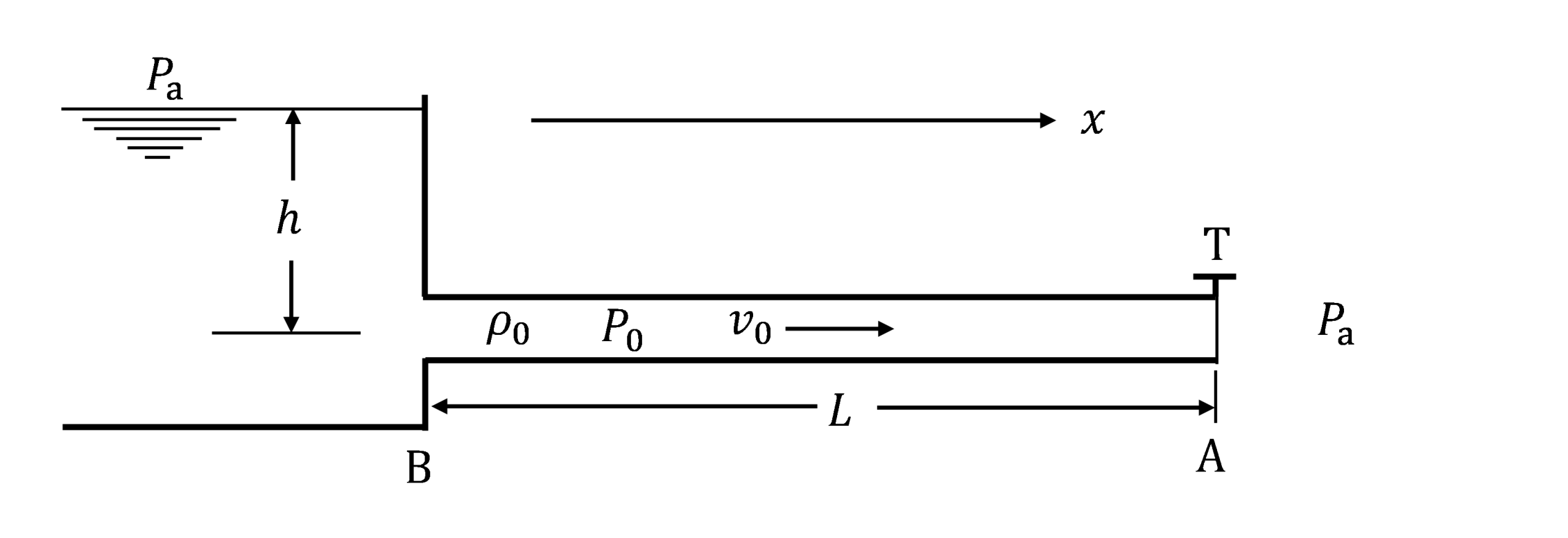
A.1 The excess pressure is related to the velocity change by . The speed of propagation is given by . Find , , and . [1,6 т.]
A.2 Calculate values of and for the case of water flow with and . [0,6 т.]
Part B. A Model for the Flow-control Valve (1.0 points)
Fig. 2 shows a model for control valve T and the liquid flow through it. The valve is taken to be a short section of length and inner radius near the end A of the pipe. Its cone-shaped outlet has an orifice of radius and opens into the atmosphere at pressure . Effects of gravity on the efflux are to be neglected.
The liquid is to be regarded as incompressible and the flow as steady with liquid element at the valve inlet having velocity , pressure , and density . In Fig. 2, stream lines and normal lines are drawn only as an aid for visualizing the flow pattern.
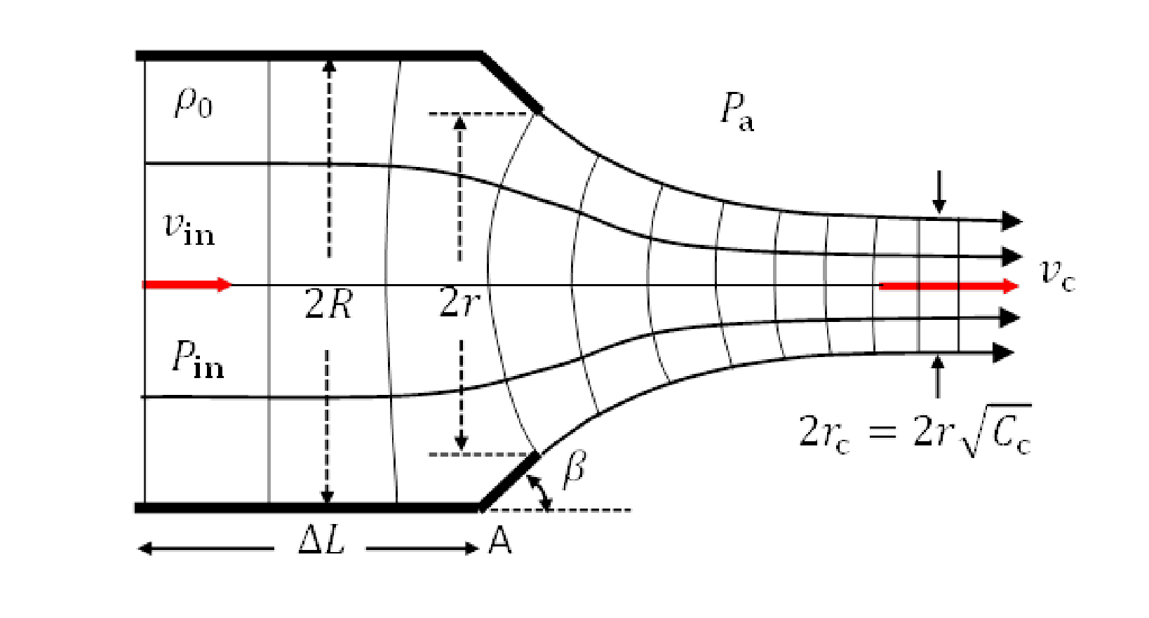
It is known that, after leaving the valve into the atmosphere, the cross section of the flow will contract until it reaches a minimum where the stream lines are again parallel. At this point of minimum, the flow velocity is and the cross section of the flow has a radius . Here , called the contraction coefficient, depends on the ratio and the cone angle as shown in Table 1.
| 0.00 | 0.746 | 0.611 |
| 0.20 | 0.747 | 0.616 |
| 0.30 | 0.748 | 0.622 |
| 0.40 | 0.749 | 0.631 |
| 1.00 | 1.000 | 1.000 |
Table 1. Contraction Coefficients for Orifices
B.1 Find the excess pressure at the valve inlet where the stream lines are parallel. Give your answer in terms of , , , , and . [1 т.]
For all tasks in Part C and Part D, we consider the reservoir-pipe system in Fig. 1 and make the following assumptions:
- Speed of propagation and density of liquid are given constants independent of flow velocity. The ambient atmospheric pressure and the acceleration of gravity are constant.
- Initially, the valve is fully open and the flow in the pipe is steady with fluid pressure and velocity .
- As in Fig. 1 and Fig. 2, the pipe has length and radius . The valve T is a circular opening of variable radius with angle and its length is negligible so that the valve inlet is effectively at the end A of the pipe. Effects of gravity on the efflux are negligible.
- Liquid in the reservoir is quasi-static so that its pressure near the pipe entrance B remains constant and we assume that the variation of fluid pressure across the pipe is negligible so that the flow is one-dimensional throughout the pipe.
- The model outlined in Part B may be used to determine the excess pressure at the valve inlet.
Part C. Water-Hammer Effect due to Fast Closure of Flow Control Valve (1.8 points)
Refer to the reservoir-pipe system in Fig. 1. When liquid flow in the pipe is obstructed by complete or partial closure of the valve, a pressure wave starts traveling upstream. It gets reflected at the reservoir end of the pipe and travels back to the valve and gets reflected there. Then another pressure wave is generated and the process just described is repeated. This causes a sequence of sudden pressure surges and dips for liquid element next to the valve and is referred to as water-hammering.
C.1 Refer to Fig. 1 and Fig. 2. Find the pressure and velocity of the steady flow in the pipe when valve T is fully open (). Give answers in terms of , , , and . [0,6 т.]
C.2 Consider the same steady flow as in task C.1 with pressure and flow velocity . Now, at , the valve is closed () instantly. A pressure wave heads toward the reservoir with speed of propagation . Take note . Let . What are the fluid pressure and flow velocity in the pipe when is getting very close to each of the instants and ? [1,2 т.]
Part D. Water-Hammer Effect due to Slow Closure of Flow Control Valve (5.0 points)
Consider again the same steady flow as in task C.1 with pressure and flow velocity . Now we close the valve slowly and adopt a finite-step approach to simulate the closing process.
Starting at time , the instant reduction of the radius of the valve (see Fig. 2) is carried out sequentially at a time interval . Immediately after each instant reduction of radius, the flow in the valve region is approximated to be steady as in Part B. The pressure and velocity at the valve are then different from those of the rest of the flow in the pipe.
For each closing step , its duration and the radius of the valve opening are specified in Table 2 along with the symbols used to represent the corresponding fluid pressure and flow velocity at the valve.
| closing step | time interval of step | ratio | pressure at valve when | flow velocity at valve when |
|---|---|---|---|---|
Table 2. Valve closing steps
Take fluid density and speed of propagation as constants. Let . Define and . Make sure to enforce the approximation .
D.1 Obtain an equation which expresses in terms of , , and . It must be valid for all steps specified in Table 2. For , obtain also an equation which allows to be computed if both and are known. [3 т.]
D.2 Apply the result of task D.1 to water flow with . Use the graph paper provided in the Answer Sheet to make all plots of versus . Be sure to draw lines and curves intersecting at points having coordinates which give the values of and for steps . On the plot, label each point of intersection with the value of to which it corresponds. From the graph, estimate values of and (both in units of MPa) for . [2 т.]
Отговори
A.1
The official solution also accepts when the bulk modulus is defined through .
A.2
B.1
C.1
C.2
D.1
D.2 ρ0cvn / ΔPn in MPa: n = 1: 5.8 / 0.62; n = 2: 3.8 / 1.0; n = 3: 1.7 / 1.1; n = 4: 0.0 / 0.64
Values as printed in the official solution table; its n = 1 entry ρ0cv1 = 5.8 MPa differs from v1 = 3.6 m/s × ρ0c = 5.4 MPa and from the appendix value 5.37 MPa.
Решение
Solution
Water Hammer
Part A. Excess Pressure and Propagation of Pressure wave
A.1 (1.6 pt) Excess pressure and speed of propagation of the pressure wave
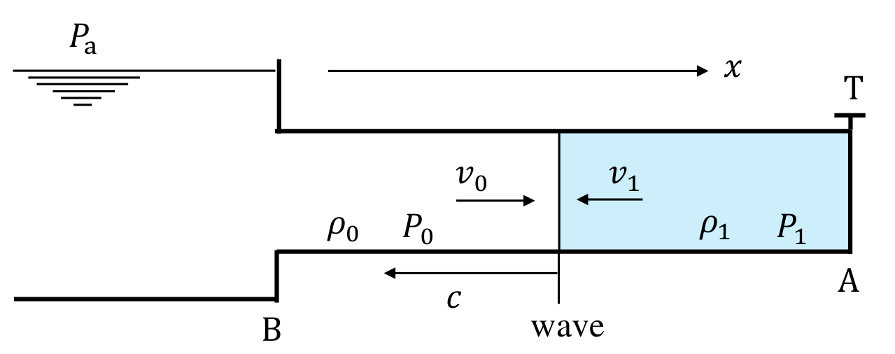
When the valve opening is suddenly blocked, fluid pressure at the valve jumps from to , thus sending a pressure wave traveling upstream (to the left) with speed and amplitude . Taking positive direction as pointing to the right, the velocity of fluid particles next to the valve changes from to (). Thus the velocity change is .
In a frame moving to left (along direction) with speed , i.e., riding on the wave (see Fig. S1), velocity of fluid in the pressure wave is , while that of the incoming fluid in the steady flow ahead of the wave is . Let be the density of fluid in the pressure wave. From conservation of mass, i.e., equation of continuity, we have
or, by letting ,
Moreover, impulse imparted to the fluid must equal its momentum change. Thus, in a short time interval after the valve is closed, we must have
or
If , we have
Note that the negative sign in Eqs. (a4) and (a5) follows from the fact that the direction of propagation is opposite to the positive direction for axis (and velocity). Otherwise the sign should be positive. Note also that for a compressional wave (), the velocity imparted to the fluid particle is in the direction of propagation, while for an extensional wave (), the velocity imparted is in the opposite direction of propagation.
Eqs. (a2) and (a4) can be combined to give
From the definition of the bulk modulus , which is assumed to be constant, it follows
From Eqs. (a6) and (a7), we obtain
Thus
However, if in the definition of bulk modulus one uses the fractional change of density instead of , the result is then .* Either result is considered valid.
If , we have
*The result (a7) is pointed out by Dr. Jaan Kalda.
A.2 (0.6 pt) Values of and for water flow
Ans:
From Eqs. (a5) and (a10), we have
Putting in the given values , , , and , we have
so that is nearly 59 times the standard pressure.
Note that so that the use of approximate formulas (a5) and (a10) is justified when solving tasks in this problem.
Part B. A Model for the Flow-Control Valve
(B.1) (1.0 pt) Excess pressure at valve inlet
Ans:
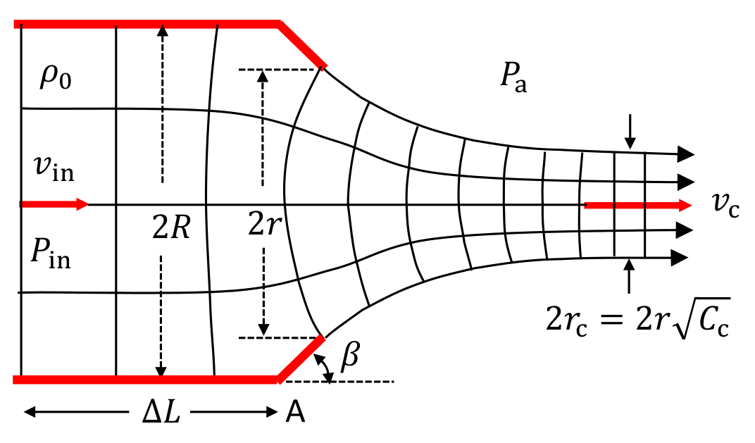
The model assumes the fluid to be incompressible. Neglecting effects of gravity, Bernoulli’s principle gives us
Equation of continuity and definition of contraction coefficient imply that
Therefore
From Eqs. (c1) and (c2), we obtain
This may be cast into a form involving only dimensionless variables:
where
Thus we see from eq. (c4) that is a quadratic function of .
Part C. Water-Hammer Effect due to Fast Closure of Flow-Control Valve
(C.1) (0.6 pt) Pressure and velocity when the valve is fully open
Ans:
According to Bernoulli’s theorem and the definition of , we have
From the second equality in the preceding equation, it follows
Furthermore, from continuity equation and , we have
Therefore
(C.2) (1.2 pt) Pressure and flow velocity just before and
Ans:
When the valve is open, the flow in the pipe is steady with velocity and pressure . The sudden closure of the valve causes an excess pressure on the fluid element next to the valve, causing it to stop with velocity . The velocity change is thus . Thus, according to Eq. (a5), the excess pressure on the fluid is given by
At time , the pressure wave reaches the reservoir. The velocity of fluid in the length of the pipe has all changed to and the fluid pressure is .
At the reservoir end of the pipe, fluid pressure reduces to the constant hydrostatic pressure . Equivalently, we may say that the reservoir acts as a free end for the pressure wave and, in reducing its excess pressure to , causes a compression wave to be reflected as an expansion wave. Relative to the hydrostatic pressure , the amplitude of the incoming pressure wave is , hence the reflected expansion wave will have an amplitude and we have
(Here we allow the pressure amplitude to have both signs with negative amplitude signifying an expansion wave.) This will cause the fluid at the reservoir end of the pipe to suffer a velocity change (keeping in mind that the direction of propagation is now the same as the axis)
Consequently, its velocity changes to
Ahead of the front of the reflected wave, conditions are unchanged and the particle velocity is still and the fluid pressure is still , but behind the wave front the particle velocity now becomes and the pressure becomes
Therefore, just moment before when the front of the reflected wave reaches the valve, the fluid in the whole length of the pipe will be under the pressure as given in Eq. (e4) , and all fluid particles in the pipe will move, as given in Eq. (e3), with velocity , i.e., the fluid in the pipe is expanding and flowing toward the reservoir.
Part D. Water-Hammer Effect due to Slow Closure of Flow-Control Valve
(D.1) (3.0 pt) Recursion relations for and
Ans:
Enforcing the approximation is equivalent to putting in all of the results obtained in task (e).
(1) Partial closing
At the valve, immediately after partial closing , fluid pressure jumps from to , causing flow velocity to change from to . The pressure and velocity changes are related by Eq. (a5):
Just before reflection by the reservoir, the fluid in the entire pipe has pressure and velocity . After reflection by the reservoir, i.e., a free end, and before the start of valve closure , the fluid in the entire pipe has pressure (Eq. (e4) with )
and velocity
(2) Partial closing
Immediately after partial closing , valve pressure changes from to , causing flow velocity to change from to . The pressure and velocity changes are given by Eq. (a5):
Using Eq. (f1), we may rewrite the preceding equation as
Just before reflection by the reservoir, the fluid in the entire pipe has pressure and velocity . After reflection by the reservoir and before valve closure , the fluid in the entire pipe has pressure
and velocity
(3) Partial closing
Immediately after partial closing , valve pressure changes from to , causing flow velocity to change from to . The pressure and velocity changes are given by Eq. (a5):
Using Eq. (f2), we may rewrite the preceding equation as
Just before reflection by the reservoir, the fluid in the entire pipe has pressure and velocity . After reflection by the reservoir and before valve closure , the fluid in the entire pipe has pressure
and velocity
(4) Partial closing
When the valve is fully shut at valve closing , the valve becomes a fixed end, so the fluid velocity at the valve changes from to . The pressure at the valve is then given by Eq. (a5):
Finally, if we take note of the fact that and , then all equations obtained above relating excess pressures and velocity changes after valve closings all have the same form:
To solve for , we note that, from Eqs. (c3) and (c5), we have another relation between and :
where represents for and
Combining Eqs. (f7) and (f8), we have a quadratic equation for :
which can be solved readily using the formula
If both and are known, Eq. (f11) may be used to compute and then find by using Eq. (f8). Therefore, Eq. (f7) may be solved iteratively starting with until . For , we know , so Eq. (f7) may be used directly to find .
Note that, from Eq. (f8), is a quadratic function of , so that if is known, then may be computed using Eq. (f11) and then may again be computed using Eq. (f8).
(D.2) (2.0 pt) Estimating and by graphical method
Ans:
To solve Eqs. (f7) and (f8) using graphical method, we rewrite them as follows:
In a plot of vs. , Eq. (g1) and Eq. (g2) correspond to a line passing through the point with slope and a parabola passing through the origin, respectively. Thus one may readily obtain the solutions for each step of valve closing by locating their points of intersection, starting with . The result is shown in the following graph.
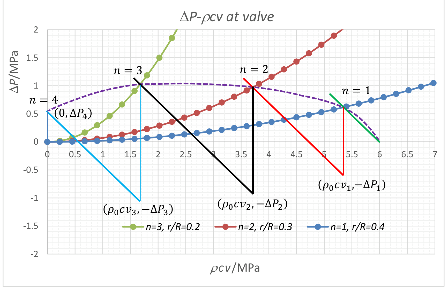
Excess Pressures and particle velocities at the valve for slow closing
| 0 | 1.00 | 1.00 | 0.0 | 4.0 | 6.0 | 0.0 | 0.0 |
| 1 | 0.40 | 0.631 | 97.1 | 3.6 | 5.8 | 0.62 | 10 % |
| 2 | 0.30 | 0.622 | 318. | 2.5 | 3.8 | 1.0 | 17 % |
| 3 | 0.20 | 0.616 | 1646. | 1.1 | 1.7 | 1.1 | 18 % |
| 4 | 0.00 | 0.0 | 0.0 | 0.64 | 11 % |
Appendix
(The following table and graph are for reference only, not part of the task.)
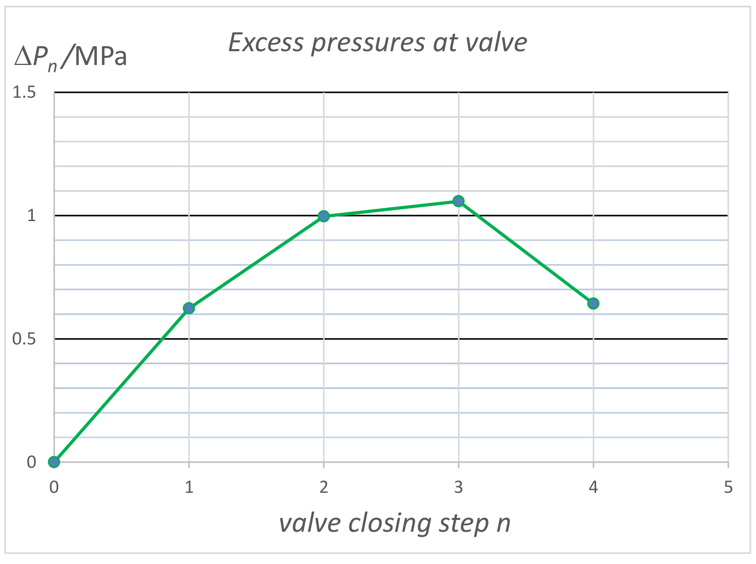
For , , and , the results for and are shown in the following table and graph. They are computed according to equations given in task (f). Note that for a sudden full closure of the valve, we have .
Excess Pressures and particle velocities at the valve for slow closing
| 0 | 1.00 | 1.00 | 0.0 | 4.0 | 6.0 | 0.0 | 0.0 |
| 1 | 0.40 | 0.631 | 97.1 | 3.58 | 5.37 | 0.624 | 10 % |
| 2 | 0.30 | 0.622 | 318. | 2.50 | 3.75 | 0.997 | 17 % |
| 3 | 0.20 | 0.616 | 1646. | 1.13 | 1.695 | 1.06 | 18 % |
| 4 | 0.00 | 0.0 | 0.0 | 0.643 | 11 % |
Оригинал в Архива: Theory Q1 english.pdf · официални решения: Theory Q1 solution.pdf