BPO 2019, Теория — Задача 4
1st Balkan Physics Olympiad – 2019 BPO · 14 юли 2019 г. · 25 т.
Условие
An electric circuit consists of four resistors and two switches (see the figure below). Let’s denote the state of the switch with “0” if it is opened, and with “1” if it is closed (in the figure both switches are opened but this may not be true for the initial state of the circuit). The initial states of the switches are unknown. The resistance between the two ends A and B of the circuit is measured. Its initial resistance (state “” of the circuit) is . The switch K1’s state is reverted and the resistance of the circuit remains the same, . After that, the switch K2’s state is reverted and the resistance of the circuit becomes . Finally, the switch K1’s state is once again reverted and the resistance of the circuit becomes .
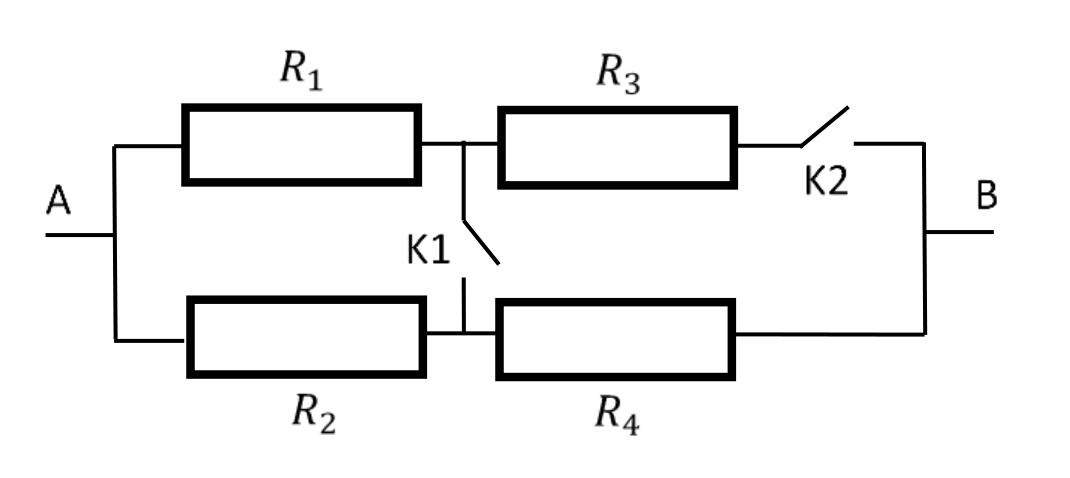
From the available experimental data, calculate the values of the resistances of the four resistors in the circuit and the initial state of each of the two switches. Fill your answer in the table below.
| State of the circuit | State of K1 | State of K2 | Ω |
|---|---|---|---|
| 240 | |||
| 240 | |||
| 400 | |||
| 280 |
| Resistor | Value, Ω |
|---|---|
Initial states of K1, K2 [2 x 2,5 points] [5 т.]
Resistor values [4 x 5 points] [20 т.]
Отговори
- Initial states of K1, K2 K1 = 1, K2 = 1 (both closed)
- Resistor values R1 = 450 Ω, R2 = 300 Ω, R3 = 150 Ω, R4 = 100 Ω
Решение
As after the switching of the K1 the resistance of the circuit remains the same, the potentials on the both ends of K1 are equal (voltage on K1 is zero). This situation is only possible when the initial state of К2 is ”1”. Later, as the , it can be concluded that the last state of K1 is ”1”. So, using these conclusions we can fill the state of the switches for all states of the circuit (see the table).
Now we can start calculations of the values of the resistors. As in the beginning both switches are closed and the opening of the K1 does not change the circuit resistance, it follows and . The relations of the currents are and . From these equations we can obtain that . To minimize the above expressions, we can note , , let , then .
For circuit state “”: . After simplification (1).
For circuit state “”: . (2)
For circuit state “”: . (3)
Substituting (2) in (1), , then . Subtracting (3) from (2), . After simplification, . Substituting with the obtained value, . Now substituting both and with their values in (2), , we obtain . So, the final values of the resistor are, , , , and .
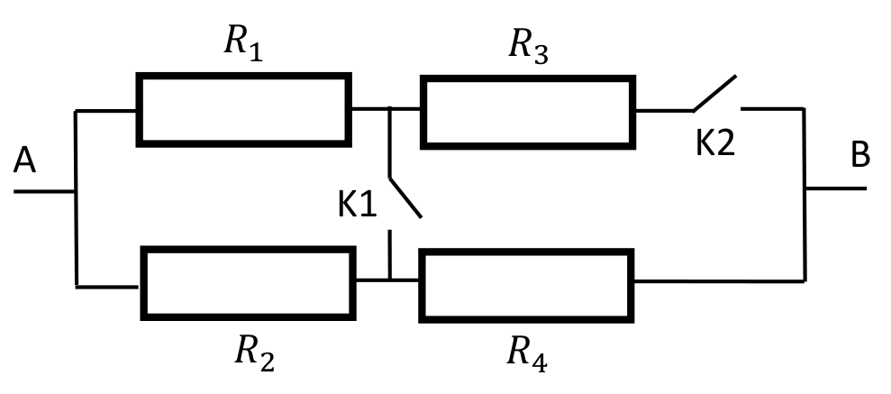
The answer is given in the table below.
| State of the circuit | State of the K1 | State of the K2 | , Ω |
|---|---|---|---|
| 1 | 1 | 240 | |
| 0 | 1 | 240 | |
| 0 | 0 | 400 | |
| 1 | 0 | 280 |
| Resistor | Value, Ω |
|---|---|
| 450 | |
| 300 | |
| 150 | |
| 100 |
Оригинал в Архива: problems.pdf · официални решения: solutions.pdf