BPO 2023, Теория — Задача 4. Electric circuit
5th Balkan Physics Olympiad, BPO 5 - Albania, 24 June 2023, Durrës, ALBANIA — Problems · 24 юни 2023 г.
Условие
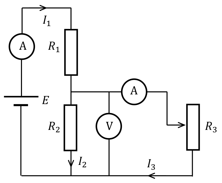
The circuit diagram shown in the figure contains a battery with voltage , two resistors of fixed value and , one resistor , the value of which can be changed, one voltmeter and two ammeters. A series of measurements were made at different values of the resistor , which are given in the table below. The measured electric currents are given in the figure (). From the data presented, calculate (all additionally calculated data must be present in the empty columns of the table):
| N | /mA | /mA | /V | |||||
|---|---|---|---|---|---|---|---|---|
| 1 | 5.73 | 5.46 | 0.545 | |||||
| 2 | 5.31 | 4.62 | 1.38 | |||||
| 3 | 4.88 | 3.75 | 2.25 | |||||
| 4 | 4.58 | 3.16 | 2.84 | |||||
| 5 | 4.36 | 2.73 | 3.27 | |||||
| 6 | 4.20 | 2.40 | 3.60 | |||||
| 7 | 4.07 | 2.14 | 3.86 | |||||
| 8 | 3.97 | 1.94 | 4.07 | |||||
| 9 | 3.75 | 1.50 | 4.50 |
A. The value of the resistance . [2 т.]
B. Using suitable variables, represent some of the measurements on such a graph that the values of voltage and resistance can easily be obtained. Draw the dependence of the two variables on the graph paper provided. [4 т.]
C. Using the obtained graph from B, calculate the values of the voltage and the resistance . [2 т.]
D. Let's define the efficiency of the circuit as the ratio of the electrical power dissipated in the resistor to the power dissipated in the entire circuit. Draw the dependence of the efficiency on the value of the resistance in the second graph paper provided. [5 т.]
E. Using the obtained graph from D, determine the maximal value of the efficiency , as well as the value of for which it is obtained. [2 т.]
F. If , calculate the theoretical maximum for the efficiency . [5 т.]
G. Determine the value of (in terms of ) for which this maximum is obtained. [4 т.]
H. Compare the theoretical and experimental results (the values of and ). [1 т.]
Отговори
A. 2000 Ω
Averaged value printed as R2 = 2002 Ω ≈ 2000 Ω.
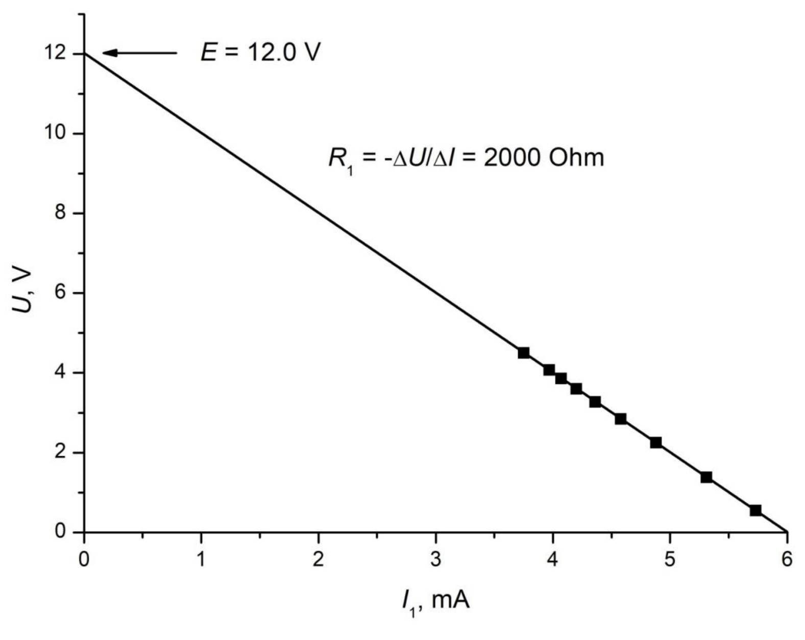
B. Plot U against I1: a straight line U = E − R1 I1.
C. E = 12.0 V, R1 = 2000 Ω
D. R3 = U/I3, η = U·I3/(E·I1); values in the table of the official solution.
E. η ≈ 17%, R3 ≈ 1350 Ω
F.
G.
H. Theory: η = 17.2%, R3 = 2000 Ω/√2 ≈ 1414 Ω — in excellent agreement with the experimental values.
Решение
BPU 2023 problem proposal
by Miroslav V. Abrashev
Sofia University, Faculty of Physics, 5 James Bourchier Blvd., 1164 Sofia, Bulgaria
Electric circuit (Solution)
A circuit diagram is given in the figure. It contains a battery with voltage , two resistors of fixed value and , one resistor whose value can be changed, one voltmeter and two ammeters. A series of measurements were made at different values of the resistor , which are given in the table below. The notations of the measured electric currents are given in the figure. From the data presented, calculate (all additionally calculated data must be present in the empty columns of the table):
| N | , mA | , mA | , V | , Ω | , Ω | , % | ||
|---|---|---|---|---|---|---|---|---|
| 1 | 5.73 | 5.46 | 0.545 | 2019 | 99.8 | 4.33 | ||
| 2 | 5.31 | 4.62 | 1.38 | 2000 | 299 | 10.0 | ||
| 3 | 4.88 | 3.75 | 2.25 | 1991 | 600 | 14.4 | ||
| 4 | 4.58 | 3.16 | 2.84 | 2000 | 899 | 16.3 | ||
| 5 | 4.36 | 2.73 | 3.27 | 2006 | 1198 | 17.1 | ||
| 6 | 4.20 | 2.40 | 3.60 | 2000 | 1500 | 17.1 | ||
| 7 | 4.07 | 2.14 | 3.86 | 2000 | 1804 | 16.9 | ||
| 8 | 3.97 | 1.94 | 4.07 | 2005 | 2098 | 16.6 | ||
| 9 | 3.75 | 1.50 | 4.50 | 2000 | 3000 | 15.0 |
a) (2 points) The value of the resistance of resistor is calculated as . (0.5 p) Calculated values are given on the table. (1.0 p) The averaged value is . (0.5 p)
b) (4 points) As , the dependence is straight line. (0.5 p) It crosses the ordinate at and has a slope . (0.5 p) The graph of the dependence is given below. (3.0 p)
c) (2 points) From the obtained graph we calculate the values of the voltage V (1.0 p) and the resistance . (1.0 p)
d) (5 points) The value of the resistor is . (0.5 p) The so defined efficiency of the circuit is . (0.5 p) The calculated values are listed in the table. (1.0 p) The graph of the dependence of the efficiency on the value of the resistance of the resistor is given below. (3.0 p)
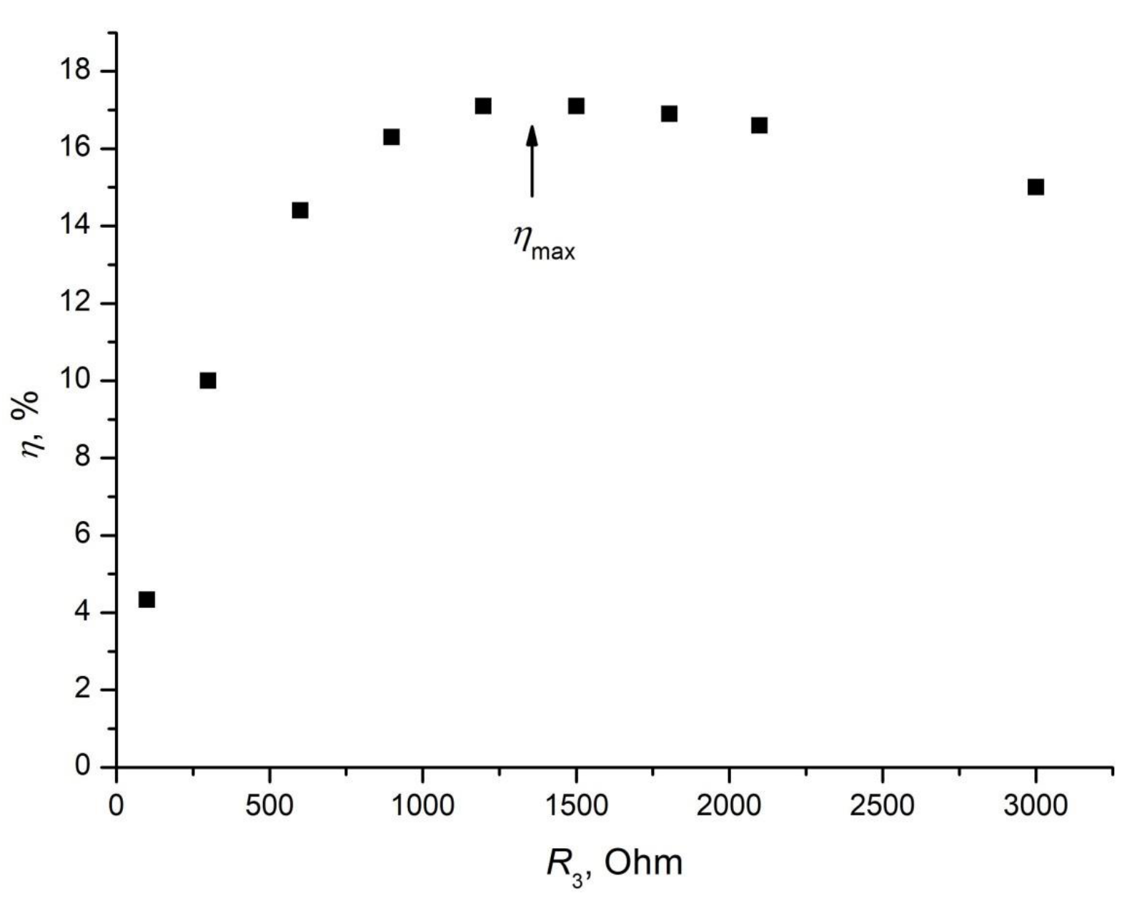
e) (2 points) It is seen that the maximum of is somewhere in the interval (1200 Ω, 1500 Ω), (0.5 p) but as the dependence near the maximum is rather flat, it cannot be determined precisely from the presented data. (0.5 p) Good values are 17%, (0.5 p) and Ω. (0.5 p)
f) (5 points) The efficiency of the circuit is . (0.5 p) In the simpler case , . (0.5 p) As , . As , . (0.5 p) Substituting these results in the equation for the efficiency, . (0.5 p) After simplifying the expression . (0.5 p) This expression can be written as a quadratic equation with variable , . (0.5 p) As for the maximal there is only one solution of , then the discriminant of this quadratic equation must be zero: . (0.5 p) The new equation for is quadratic one: . (0.5 p) This quadratic equation has roots . As , (0.5 p) only the root is a solution. (0.5 p)
g) (4 points) Substituting the obtained value of in the quadratic equation for , , we obtain . (1.0 p) The discriminant of this quadratic equation is zero. (1.0 p) Then . (1.0 p) After simplification . (1.0 p)
h) (1 point) The theoretical values of =17.2% (0.5 p) and (0.5 p) are in excellent agreement with the experimental ones.
Оригинал в Архива: problems.pdf · официални решения: solutions.pdf