EuPhO 2019, Експеримент — Задача 1. Sensitivity of receiver.
Experimental Problems Text for Student: COM-A1 — Propagation of radio waves. · 1 т.
Propagation of radio waves.
Electromagnetic waves play an important role in our lives. Many technological advances are built on the propagating properties of these waves. In this experiment you are to study the propagation of radio waves in water, in air and in waveguides.
Tools.
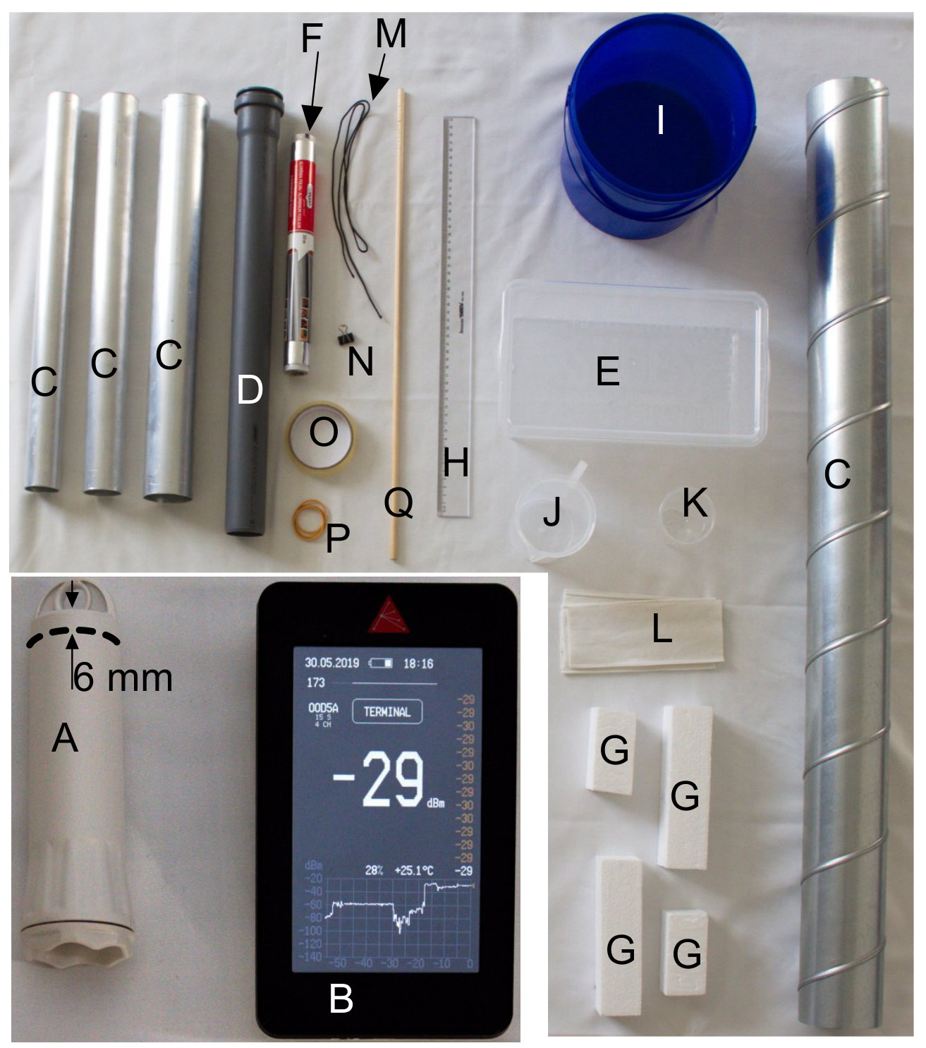
- Emitter of monochromatic radio waves in a waterproof housing (the frequency is in the range from to ) marked with label “A” in Figure 1; the wave source position is shown as a dashed line in the figure. It is paired with a receiver “B” which measures the received electromagnetic wave power and shows the result in decibels [reading in decibels ]. The receiver takes a reading every 15 seconds. The sensor position is marked with a red triangle on the device. NB! The receiver is not waterproof! The emitter housing is waterproof and sealed, and you must not open it!
- A set of metallic tubes “C” of various diameters (inner diameters , , , ).
- A plastic tube “D” which has one end sealed with a cap.
- A plastic box “E” with a flat bottom. The phase shift of radio waves passing through the walls of the box can be assumed to be negligibly small.
- A roll of aluminium foil “F”
- Four pieces of foam “G” from which you can build a screening holder for the emitter as shown in Figure 2.
- A ruler “H”.
- A plastic bucket with water “I”, a jug “J”, a plastic cup “K”, and tissues “L”.
- A thin rope “M” , a clip “N”, a roll of tape “O”, rubber bands “P” and a wooden rod “Q”.
Your emitter is paired with your receiver, and the receiver filters out the signal of all the other emitters. However, you should keep in mind that the radio waves are reflected from all the objects in the room, including human bodies, giving rise to interference of waves. So, bringing your hand near to the receiver or moving your body may affect the reading of the receiver. The received power depends also on the orientations of the receiver and the emitter. Be careful with shielding made from aluminum foil: even tiny holes and gaps (e.g. between the foil and the box in Figure 2) may cause leakage of waves.
The tasks 1–4 are independent and can be done in arbitrary order. Sketch all the experimental setups used, emphasize important design details, write down all the used formulae, tabulate all the measured data, and make graphs where appropriate. There is no need to estimate uncertainties, but try to perform measurements as precise as possible.
Waves in metallic tubes (printed before Task 3)
In the following tasks you will study the propagation of waves in metallic tubes filled with medium (water or air) in which case
where stands for the electric field vector, describes the attenuation due to dissipation in the medium (for water , for air ), and we have used cylindrical coordinates .
The function represents a standing wave across the cross-section of the waveguide. Different standing waves in the cross-section correspond to different propagation modes of the wave in the waveguide. The dispersion relation for the waves in a waveguide is given by
where is the speed of light in the medium filling the waveguide, and is a positive constant depending only on the diameter of the tube and on the propagation mode. In your experiment, all the other propagation modes except for the mode with the smallest value of can be ignored. Pay attention to the fact that a wave can propagate along the waveguide without attenuation (with a real-valued wave vector ) only if the oscillation frequency is high enough, . Equations (1) and (2) remain valid for lower frequencies yielding purely imaginary which corresponds to a decaying (evanescent) mode.
Условие
What is the lowest measurable received power (in mW)?
Решение
Внимание: Непълно решение
В архива няма официално решение на тази задача.
Оригинал в Архива: exp_pr.pdf