EuPhO 2024 — Задача 2. Task E.2 - Piezoelectric properties
Автор: Olympiads XYZ · транскрипция на официалните материали
Проверена срещу оригинала на 13.9.2026 от същия модел, който я е транскрибирал (без независима проверка)
"EuPhO 2024, Kutaisi, Georgia — Experimental Problems" · 10 т.
Внимание: Бележка към темата
Solutions-only window; statements to be assembled from the problems-document window. E.4 solution is incomplete (continues beyond page 6).
Условие
Some crystalline, electrically insulating materials, such as quartz and lead zirconate titanate, exhibit an electrical response when mechanical pressure is applied. In short, mechanical stress polarizes the crystals, which is called the piezoelectric effect. This phenomenon can be explained by the special structure of their molecules: the deformation gives each molecule an electric dipole moment. Conversely, mechanical stress is generated in the presence of an electric field, a phenomenon known as the reverse piezoelectric effect. However, in this problem, we will neglect the reverse piezoelectric effect.
This problem investigates a simple device that relies on piezoelectricity, the piezoelectric element. It consists of the piezoelectric material placed between two circular metallic plates. When a force, perpendicular to the metallic plates, is applied to the element, a force-dependent voltage appears between the plates.
Equipment (see also Fig. 1)
A Piezo element with electrical leads, attached to a wooden base plate and a cover plate with a small hole. The hole goes through the entire cover plate, such that a small part of the top electrode of the piezo element is visible through it. This electrode is thin and flexible. B Multimeter (inner resistances are given, refer to the important remarks on the next page). C 1.5 V AA battery with connector. D Capacitor of unknown capacitance, with a diode soldered to one leg (when a forward current flows through the diode, the voltage drop across it is 0.56 V). E 4 electric push-button switches (connected while pressed) on wires. F 6 crocodile clamps. G Digital scales (up to 10 kg). H Digital stop watch. I 2 different rubber balls. J Wooden stand with adjustable release mechanism. K 50 cm ruler. L Small, wooden sticks (diameter of 2 mm), in two different lengths. M Large metal screw. N Wooden clothes peg. O Pencil, pen and pencil sharpener.
Important practical remarks
- It is expected that you provide circuit diagrams with all the electrical measurements you take. Use the symbols provided in Fig. 2.
- Be careful not to short the multimeter! The internal resistances given are only valid for DC voltage measurements.
- Do not exceed a total load of 100 N of force on the piezo element.
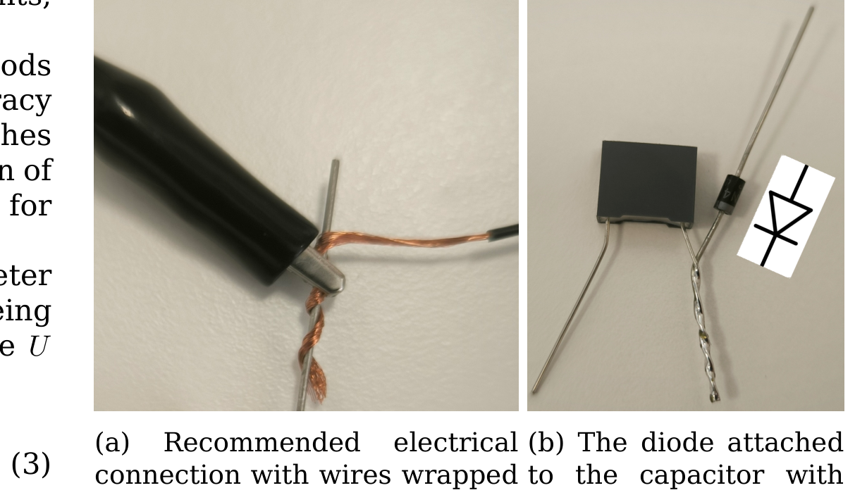
- To connect two wires, it is recommended to wrap them around each other and use the crocodile clamps to secure the connection, see Fig. 3a.
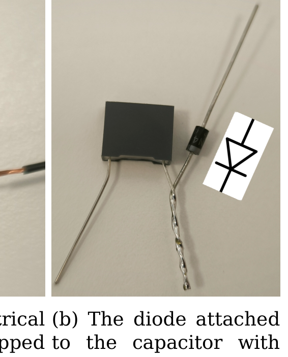
- The diode's polarity is visible in Fig. 3b.
- You can adjust the height of the release mechanism via the two screws on the back, see Fig. 4. You can also adjust the horizontal position by unscrewing the vertical nut at the release mechanism.
- Be careful not to let the bouncy ball escape. You can minimize the chances of the ball leaving your table by placing the stand with the release mechanism against one of the walls or in a corner of your desk and use the ruler as another, transparent wall that is secured with the clothes peg. If you still loose the ball, ask for assistance, do not leave your place.
- After a certain time of inactivity, the multimeter will start to beep and, after another few minutes, will shut down. You can prevent shut-down by pressing any button.
- Be aware that some regions of your table may spring back under load. It is wise to use stable regions of your table for the bouncing experiment.
- For the evaluation of a series of measurements, you are expected to plot the data.
- Only those measurements and evaluation methods that promise the highest precision and accuracy are awarded full marks. Choose your approaches accordingly while keeping in mind the precision of your tools. However, no marks are awarded for error estimation.
- When measuring DC voltages with the multimeter in a range with the smallest digit resolution being , the uncertainty of the measured value can be estimated via:
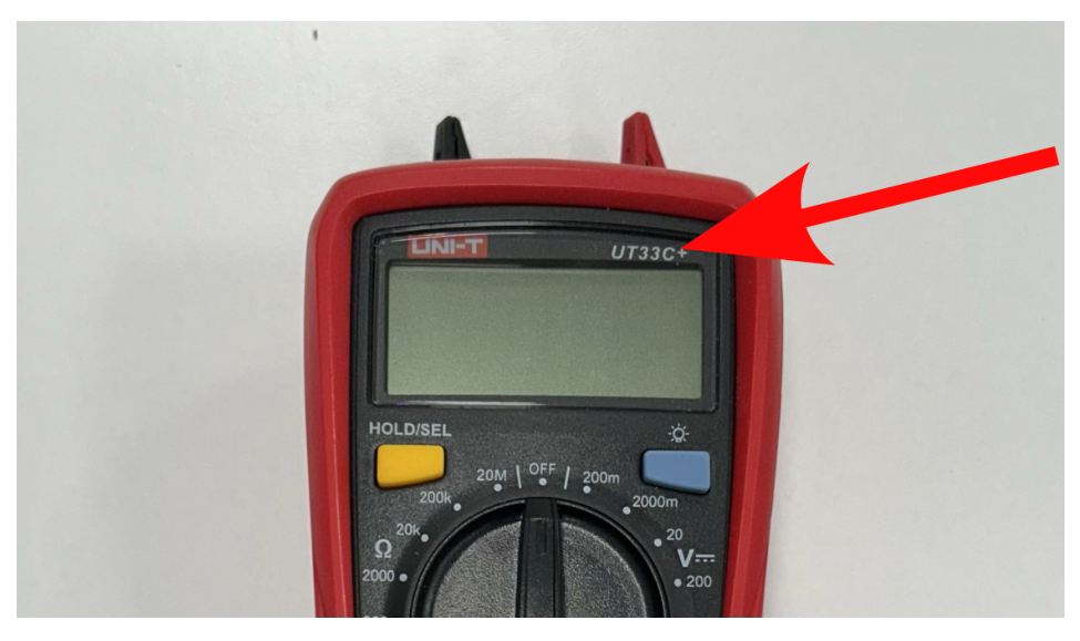
- The internal resistance of your multimeter in the DC voltmeter setting depends on the measurement range and model number. In Fig. 5, you can see where to find the model number of your voltmeter. The following table provides the internal resistances for two measurement ranges and all models.
| model number(s) | range | internal resistance |
|---|---|---|
| all models | 2 V | 11.1 M |
| UT33B+ | 200 mV | 9.65 M |
| UT33C+ | 200 mV | 9.91 M |
| UT33D+ | 200 mV | 9.70 M |

a Measure the capacitance of the capacitor (Fig. 3b). [2 т.]
b The metallic plates on the sides of the piezo element also act as a capacitor. Find the capacitance of the piezo element. [2,5 т.]
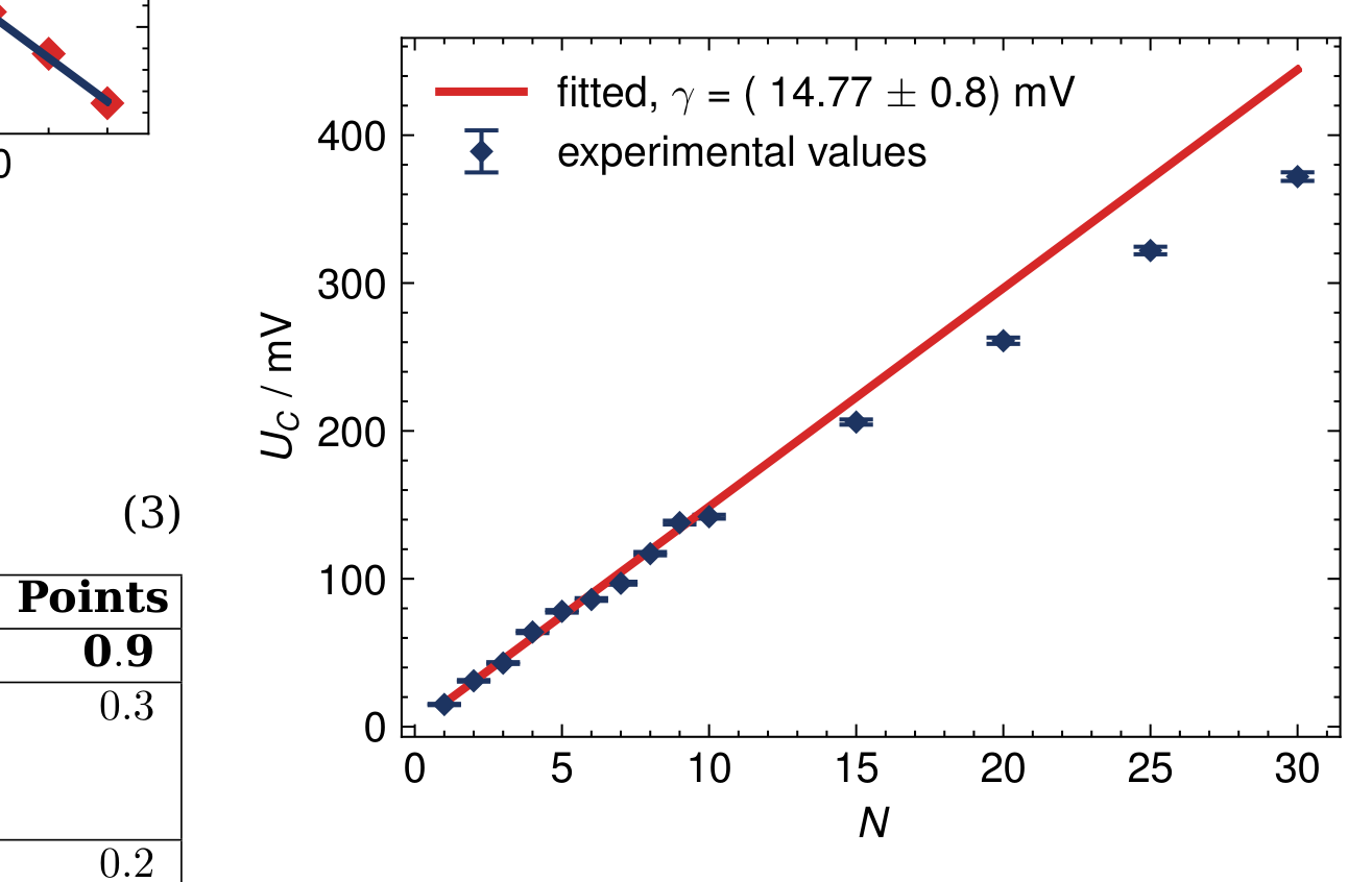
c Measure and plot how the voltage between the plates of the piezo element depends on the total perpendicular force, which is evenly distributed over the surface of the piezo via its wooden cover plate. For low forces, the dependence is linear; find the slope in this regime. [4 т.]
d The molecules of the crystals can only have polarizations lower than a certain critical value. Find the maximal (saturation) voltage of the piezo, the pressure at saturation and the maximal surface density of the charge on the surface of the piezo element. [1,5 т.]
Решение
Покажи официалното решение
Оригинал в Архива: eupho2024_experiment_problems.pdf · официални решения: eupho2024_experiment_solutions.pdf