EuPhO 2025 — Задача 1. E1 – Deep Learning (10 pts)
Автор: Olympiads XYZ · транскрипция на официалните материали
Проверена срещу оригинала на 13.9.2026 от същия модел, който я е транскрибирал (без независима проверка)
Experimental Problems Language: English · 10 т.
Внимание: Бележка към темата
Task 6 solution continues beyond this window; Tab. 5, Figures 8 and 9 and the final verification are on later pages.
Условие
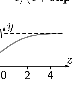
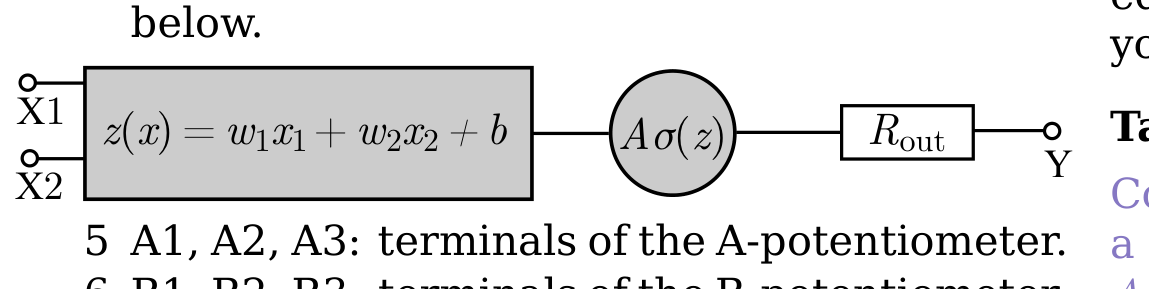
Modern ANNs (artificial neural networks) are made of billions of neurons. Each neuron transforms its input(s) to an output . First, is calculated, with real numbered weights and real numbered bias . Then an activation function is applied to to produce the final output . In the present problem you will investigate a physical model of a neuron with the electric voltages and as inputs, with the activation function being , graphed below, where is called sigmoid function.
Equipment
Important! Do not switch off any power outlets.
(i) A box containing a voltage source, an electronic circuit that models the neuron, and two potentiometers (the A-potentiometer and the B-potentiometer). The electric terminals on the box are denoted as follows:
- Two electrically connected GND terminals: the electrical ground serving as a common negative terminal for , , , and .
- : the positive terminal of the voltage source.
- X1 and X2: the positive terminals of the neuron input voltages and , respectively. The neuron output behaves unpredictably if either of these terminals has no input voltage.
- Y: the positive output terminal. It behaves like a real voltage source, consisting of an ideal voltage source of voltage and a series output resistor , and operates as shown below.
- A1, A2, A3: terminals of the A-potentiometer.
- B1, B2, B3: terminals of the B-potentiometer.
- T: a terminal not to be used in this task.
(ii) Digital multimeter with two probe wires.
(iii) Wires with banana connectors. Two or more wires could be connected to the same terminal in the box by using the holes in the banana connectors. Using the banana connectors with the multimeter may form an unstable connection. Use the alligator clamp if needed.
(iv) Graph paper. You can ask for more if needed.
Training involves optimizing the network weights to achieve desired functionality. This allows ANNs to approximate arbitrary functions. For each of the following tasks you have to approximate a different function of a single input voltage using the given equipment. Make sure that the input and output that you define are clearly marked in your circuits.
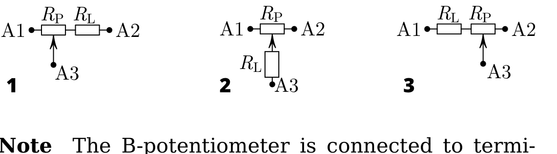
Task 1 (0.5 pts) Terminals A1, A2, and A3 are connected to the A-potentiometer and an additional load resistor . Which of the schemes below corresponds to the circuit in the box? Determine the resistances and ; document the measurements made.
Note The B-potentiometer is connected to terminals B1, B2, B3 in exactly the same way with the same resistances and , within manufacturing tolerances. [0,5 т.]
Task 2 - (0.5 pts) Sketch how the terminals have to be connected so that the neuron input voltages can be varied with the widest possible range. [0,5 т.]
Task 3 - (1.5 pts) Devise (and document) a strategy allowing you to find the combination of input voltages and that maximizes the output voltage with the least possible number of measurements, irrespectively of with which set of input voltages you start the search. Determine this maximal voltage that will be henceforth used as an approximation for the amplitude , and document your measurements. [1,5 т.]
Task 4 - (3.5 pts) Determine the weights , and the bias . Describe your measurements and document your data in a table. Estimate , , and by using a graphical proach. [3,5 т.]
Task 5 - (1.5 pts) Connect the terminal X1 directly to . Design a circuit to approximate the function , where is the voltage applied to your newly defined input terminal. Determine theoretically. Implement the circuit, take measurements and verify that your setup works as expected. Validate the value of from your data. [1,5 т.]
Task 6 - (2.5 pts) a Determine the internal series output resistance of the Y terminal. (0.5 pts)
b Design and implement a circuit to approximate the function , where . Determine theoretically. Implement the circuit and verify experimentally that your setup works as expected. Confirm the values of and from your data. (2.0 pts) [2,5 т.]
Решение
Покажи официалното решение
Оригинал в Архива: eupho2025_experiment_problems.pdf · официални решения: eupho2025_experiment_solutions.pdf