INPhO 2021, Теория — Задача 1
Indian Olympiad Qualifier in Physics (IOQP) 2020-2021 — Part II: Indian National Physics Olympiad (INPhO) · 7 февруари 2021 г.
Указания
This booklet consists of 4 pages and total of 5 questions. Write roll number at the top wherever asked.
Booklet to write the answers is provided separately. Instructions to write the answers are on the Answer Booklet.
Marks will be awarded on the basis of what you write on both the Summary Answer Sheet and the Detailed Answer Sheets in the Answer Booklet. Simple short answers and plots may be directly entered in the Summary Answer Sheet. Marks may be deducted for absence of detailed work in questions involving longer calculations.
Strike out any rough work that you do not want to be considered for evaluation. You may also use the space on the Question Paper for rough work – this will NOT be evaluated.
Non-programmable scientific calculators are allowed. Mobile phones cannot be used as calculators.
Last page of the question paper can be used for rough work.
Please submit the Answer Booklet at the end of the examination. You may retain the Question Paper.
Table of Constants
| Quantity | Symbol | Value |
|---|---|---|
| Speed of light in vacuum | ||
| Planck's constant | ||
| Magnitude of electron charge | ||
| Rest mass of electron | ||
| Value of | ||
| Acceleration due to gravity |
Note on solutions
Please note that alternate/equivalent methods and different way of expressing final solutions may exist. A correct method will be suitably awarded.
Условие
The ammeter-voltmeter method is widely used for measuring electrical resistances in the physics laboratory. In this method, the resistance is always derived from the readings and from a voltmeter and an ammeter respectively, using Ohm's law: . While using this method, it is assumed that the ammeter and voltmeter used in the setup are ideal. In this problem, we will find the pitfalls of this assumption and devise a new setup with a better performance.
The standard ammeter-voltmeter setup consists of a DC voltage source () maintained at a constant voltage, a protection resistance (), an ammeter (A), and a voltmeter (V). The unknown internal resistances of the ammeter and the voltmeter are and , respectively. Also, . We aim to measure the true value of an unknown resistor.
We consider a two commonly used circuit configurations (1) and (2) indicated by the two possible positions of the switch in the circuit diagram shown below. Let the measured values of the resistance be and in the setups (1) and (2), respectively. The relative error, , is defined as the ratio of the absolute error of the measurement to the actual value: .
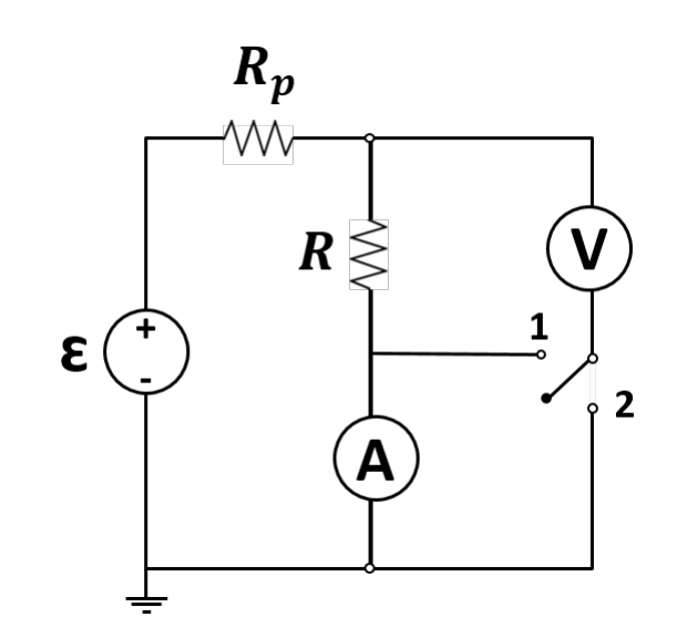
(a) Obtain the relative errors in the measurements ( and ) for each of the above configurations. [2 т.]
(b) Using exactly the same circuit elements, can you suggest a step by step procedure, with the necessary circuit diagram(s), to measure the true value of the resistance R, regardless of the values of the internal resistances of the ammeter and the voltmeter? You may use the measurements made in part (a). [4 т.]
Отговори
(a)
(b)
RA is measured with the ammeter and the voltmeter in parallel (switch in position 1 of the new configuration).
Решение
(a) Solution:
Setup (1):
Current through the ammeter
whereas the voltage corresponds to the voltage across the voltmeter-resistance combination. Thus the measured resistance
Setup (2):
Current through the ammeter
Thus
(b) Solution:
- We use the configuration shown below. When the switch is in position 1, ammeter and voltmeter are in parallel and we calculate .
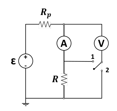
- When we use the switch in position 2, the configuration is same as position 2 of part (a).
This will give the true value of the resistance.
Оригинал в Архива: IOQP2021-PartII-Questions-en.pdf · официални решения: IOQP2021-PartII-Solutions-20210217.pdf