IOM 2018, Теория — Задача 2. «Nonlinear Trio»
Problem 2. «Nonlinear Trio» · 30 т.
Условие
In this problem, «nonlinear resistors» (aka varistors) are considered. In the case at hand, a voltage across a varistor is proportional to the square of a current flowing through the varistor (polarity is respected): . The factor is specific for a given varistor.
Part I: Nonlinearity and Direct Current.
Suppose we have three identical (with the same ) varistors, three identical sources of DC voltage with negligible internal resistances, a conventional resistor, a diode, and an almost ideal ammeter. It is known that if a varistor or the conventional resistor are connected to a single voltage source, the current through the source equals A. The elements listed above are assembled into the circuit shown in Fig. 1. A varistor is represented by a rectangle with a «wave» inside.
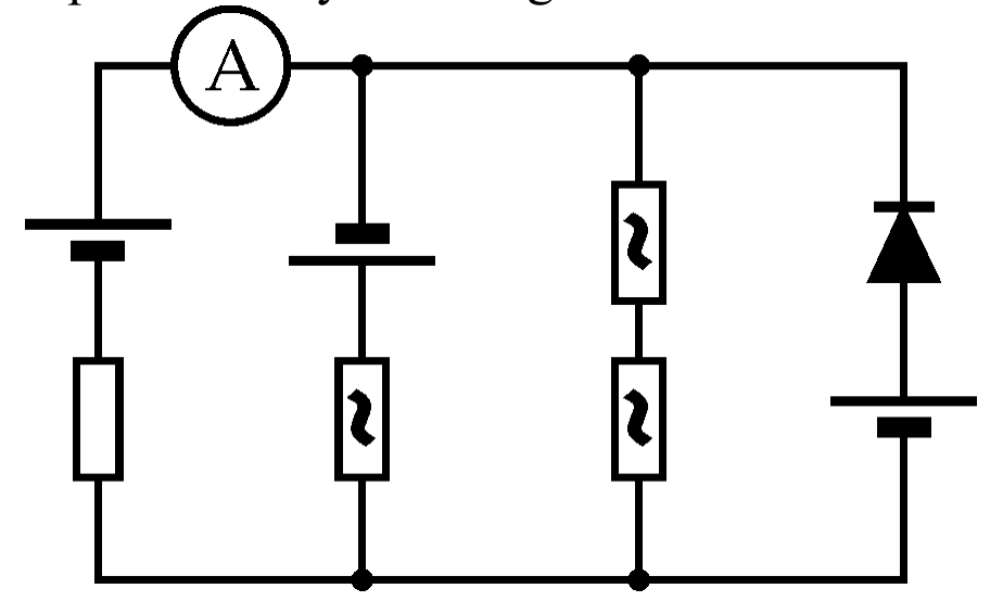
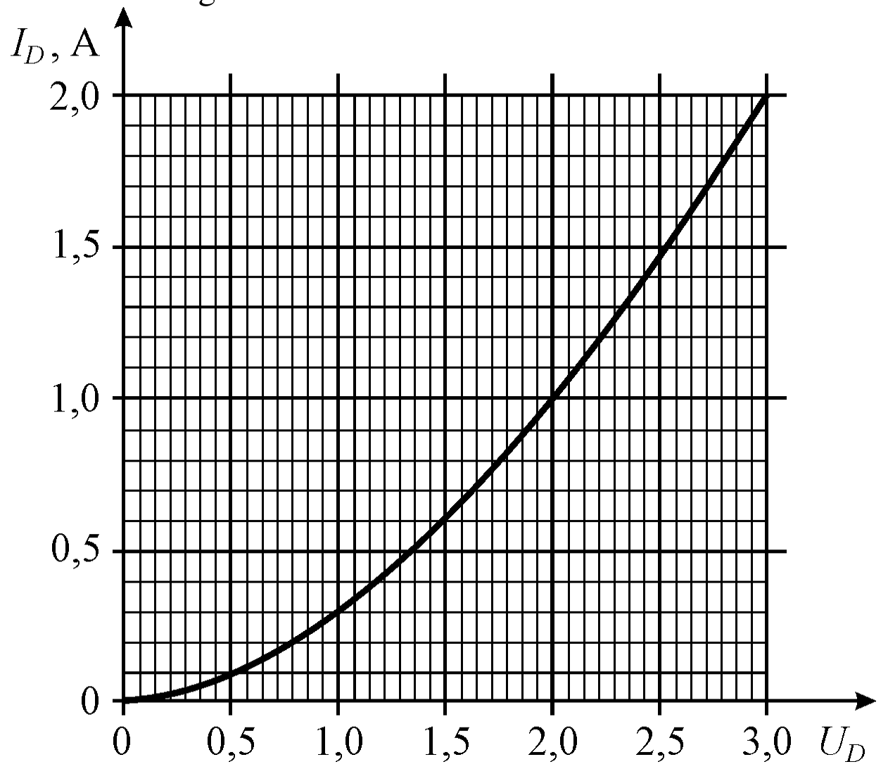
Figure 2 depicts the I-V curve of the diode. A scale of the voltage (horizontal) axis is not specified but it is known that a current equal to through the diode corresponds to a voltage which is 5 times less than the EMF of a voltage source.
1.1. Write down a complete set of equations for the currents flowing in the circuit branches which appear vertical in Fig.1. The equations must include a voltage across the parallel branches together with an EMF of a voltage source, the resistance of the conventional resistor, and the factor . [1 т.]
1.2. Determine the ammeter readings with an accuracy of at least 10%. Neglect a resistance of connecting wires. Write the answer in amperes and indicate a confidence interval of the result. [4 т.]
Part II: Nonlinearity and Capacitor Discharge.
Now let us connect a varistor with another factor to a charged capacitor (see Fig. 3). If the connecting wires are sufficiently cooled down, they become superconductors and the capacitor will completely discharge in a time s. Properties of the varistor are independent of temperature.
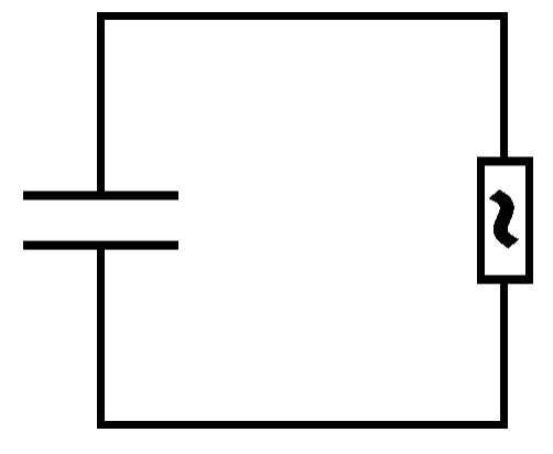
2.1. Express via the capacitance , the initial charge of the capacitor, and the factor of the varistor. [2 т.]
2.2. If the capacitor discharges only via the connecting wires at room temperature, the charge decreases by a factor of in a time ms ( is the base of the natural logarithm). What is the relation between and the resistance of the wires? Derive the corresponding equation. [1 т.]
2.3. Determine a time in which the circuit current decreases from the initial value to , providing the capacitor discharges via the varistor at room temperature. Write down the answer in terms of , , , , and . [3 т.]
2.4. Determine a time in which the capacitor charge decreases by a factor of , providing the capacitor discharges through the connecting wires and the varistor at room temperature. Derive a formula in which is expressed via , , and , and evaluate the numerical value (in ms) with at least 10% accuracy. [4 т.]
Part III: Nonlinearity and Damped Oscillations.
In the next experiment the circuit consists of a capacitor, a varistor (with another factor ), and a superconducting inductor (see Fig. 4). The connecting wires are also maintained in the superconducting state. In this case, damped oscillations begin in the circuit and when the circuit current vanishes for the first time, the charge of the capacitor turns out to be less by 10% than its initial value.
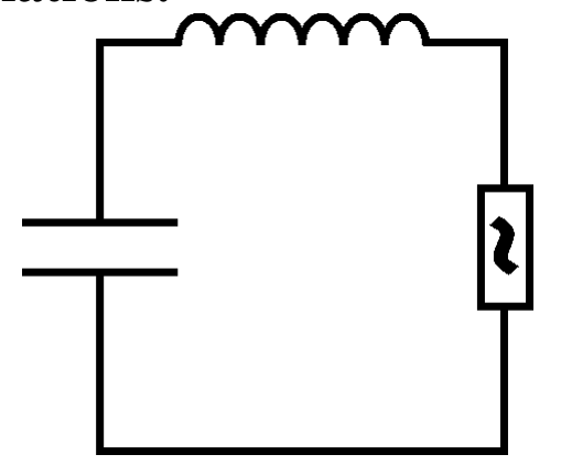
3.1. Suppose that at some time before the first half of the oscillation cycle ended, the capacitor charge had decreased from an initial value to . What is the circuit current at this moment? Express the answer in terms of , , , , and . It would be useful to remind that solution of a complex nonlinear equation of motion in mechanics is often significantly simplified if one tries to transform it into an equation for the rate of energy change. [4 т.]
3.2. Determine how much of the initial capacitor energy was released as heat in the varistor until the capacitor charge first became zero. Evaluate the answer (in percent) with at least 10% accuracy (i.e. the error must not exceed 10% of the result). [4 т.]
3.3. What part of the initial capacitor energy was released as heat in the varistor until the current first became zero? Evaluate the answer in percent. [3 т.]
3.4. What part of the initial capacitor energy was released as heat in the varistor by the time the capacitor charge became zero for the second time? Evaluate the answer (in percent) with at least 10% accuracy (i.e. the error must not exceed 10% of the result). [4 т.]
REMINDER. Factors of varistors used in different parts of the problem are different!
Решение
Proposed Solution
Part I
1.1. Let us introduce the following notations: let be a common voltage across four parallel branches of the circuit (between the upper and the lower conductors), and be the currents in the circuit branches (numbering from left to right, positive directions of the currents are shown by arrows in Fig. 1a).
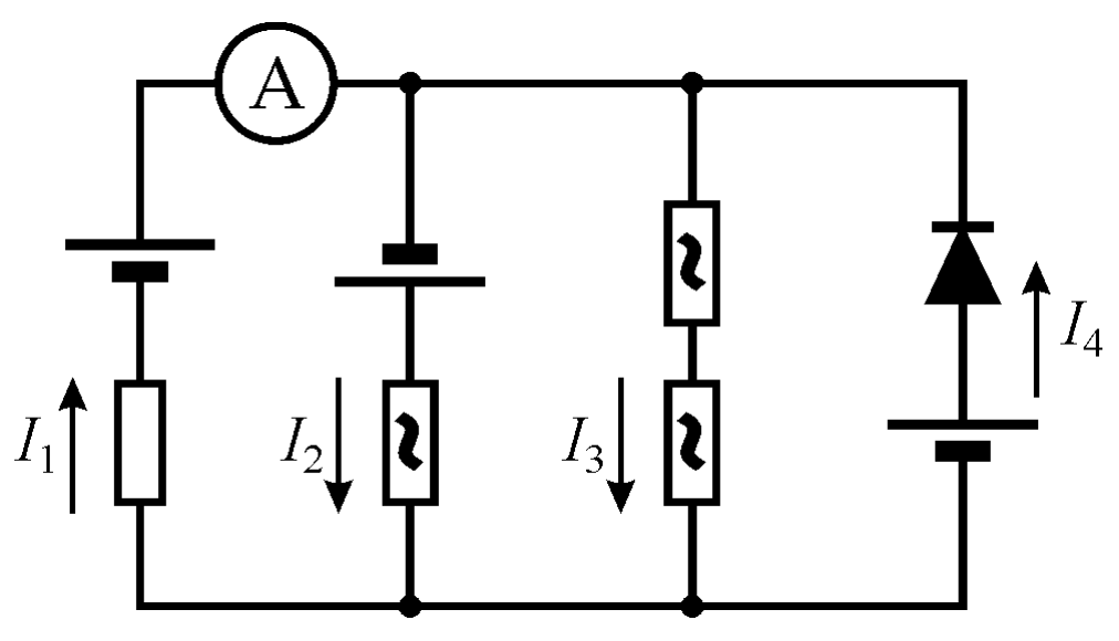
Let be a resistance of the conventional resistor. According to the problem statement, . Since the current and voltage of the varistor are related as , one obtains that . Suppose that the I-V characteristic of the diode is given by an equation . Then, the currents in the circuit branches can be expressed via the voltage across them as:
where (the correctness of the chosen directions of the currents is verified in the course of the solution). Besides, the currents must satisfy the law of conservation of charge, i.e. . Thus, can be found from an equation .
1.2. According to the problem statement, the current through the diode equals when the voltage across the diode is 5 times less than . Therefore, , which allows one to «shift» the diode I-V curve on a diagram in which the currents through other branches are plotted (the red curve in Fig. 1b) and to solve the above equation graphically: plot the left-hand side of the equation and then plot the right-hand side by adding the contributions of the currents at each .
According to the diagram, the ammeter readings (corresponding to the current through the resistor) are A. The error meets the accuracy requirement specified in the problem statement even under a moderate construction accuracy, in fact, it can be improved.
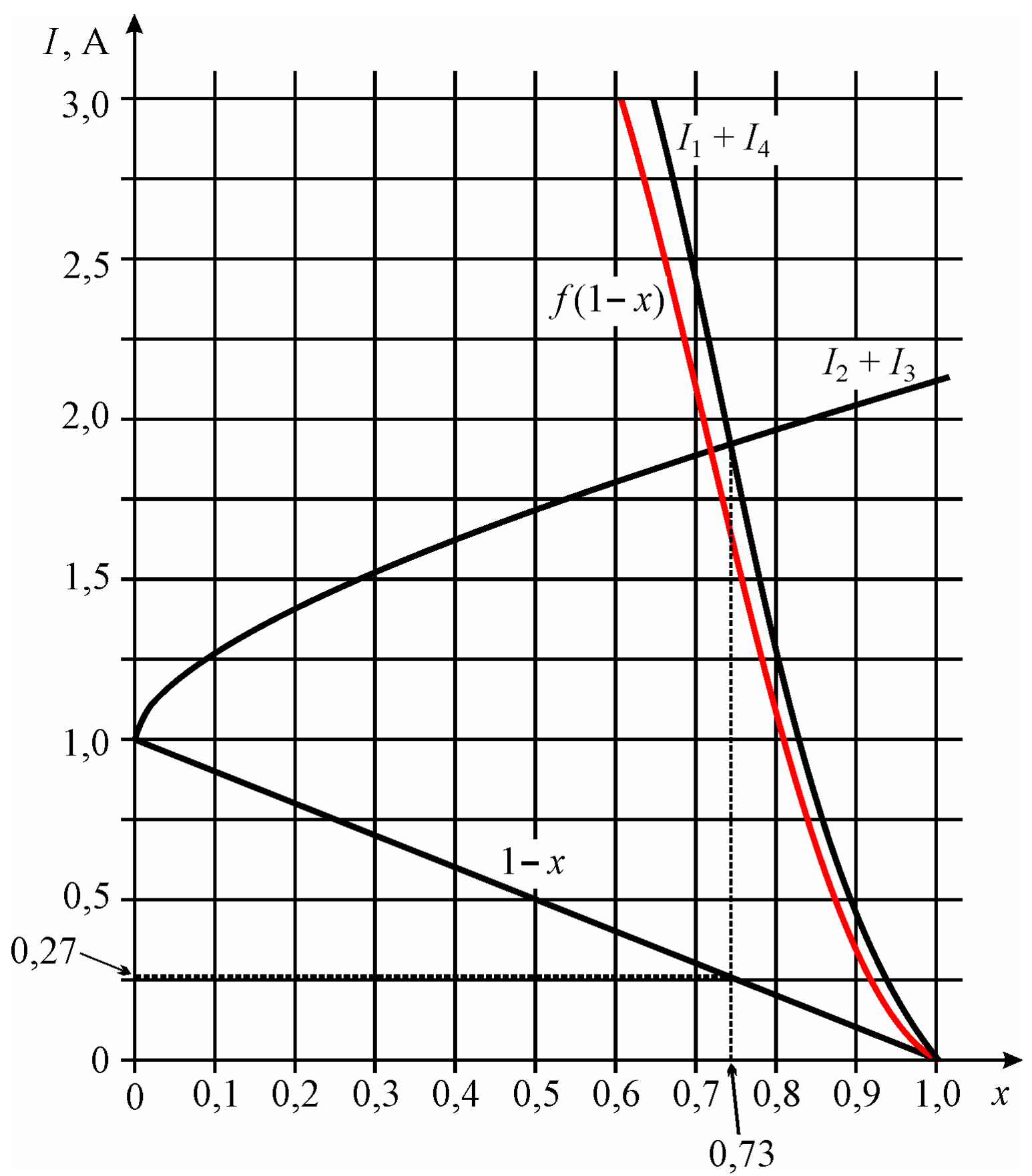
Note: The result obtained by the graphical method can be significantly improved by using an «algebraic» approach. Even a crude construction of the plot makes it obvious that the answer is close to , and the current flowing through the diode is near 1,5 A. One can also notice that the tangent of the I-V curve near this value of the current is very close to 1. Then one can do the following. Replace the diode I-V curve on the second plot near with . Assuming and expanding all functions up to terms linear in , one obtains . It follows that , so the correction is indeed small and a computational error here is less than 3%. A graphical error can be estimated as 2%, hence, A. One can do the next step and evaluate the tangent to the diode I-V curve at the current equal to 1,6 A (this is the current through the diode obtained by the «crude» approximation) and evaluate the second derivatives, then the I-V curve can be described by a quadratic expression. In so doing, a computational error becomes negligible compared to the graphical error and the accuracy improves even more: . However, the accuracy of graphical method itself suffices for solving the problem provided the construction is accurate. Nevertheless, there is an additional bonus reserved in evaluation criteria for those contesters who would reduce the error two-fold compared to the error specified in the problem statement. Notice that an «almost precise» answer obtained by means of an analytic equation for the diode I-V curve (this equation is known to the authors) is: A.
Part II
2.1. Again, we use the nonlinear current-voltage relation of a varistor, . A discharge current flowing through the varistor via superconducting wires is related to the capacitor charge as (the discharge current does not change direction and can be considered as positive). An equation for the rate of charge change is (the capacitor charge decreases), so the total discharge time equals (here is the initial capacitor charge).
2.2. It is clear from the problem statement that is a time constant of the capacitor discharging through wires at normal temperature, i.e. .
2.3. Let us write an equation for the discharge through the varistor and wires of a resistance .
In this case, , so . Therefore, the time, in which the discharge current decreases from to , equals .
2.4. The initial current is determined from the equation . Then the current at the time when the charge has decreased by a factor of equals . It is easy to see that , so the desired time equals
One can evaluate the numerical value using this formula (this gives ), or one can try to simplify the formula first. To do this, notice that and . This gives ms. The answer clearly meets the accuracy requirements.
Comments: The result is interesting since a small resistance (numerically, is only 5% of ) changes the result almost by 30%! Actually, the resistance of wires changes significantly the behavior of only near : it «stretches» the discharge in time.
Part III
3.1. Let us write an equation of oscillations in the circuit. As before, assume the discharge current of the capacitor to be (i.e. for now we limit a solution to the first «half-cycle»): . To analyze the rates of change of the capacitor charge and the inductor energy it would suffice to relate the charge and the current, if time dependence of these quantities is not necessary. Now, let us recall how one evaluates the rate of change of kinetic energy in mechanics: . By analogy, the above formula for the time derivative of the current can be transformed as: . Then, one obtains an equation for :
The same equation follows if one applies a similar argument to the rate of change of the energy stored in the circuit.
The right-hand side can be removed by means of a linear substitution which transforms the equation into identity:
Then one can change variables by writing:
so the equation becomes . Obviously, , (where ), so during the first «half-cycle» of oscillation is:
If is the initial capacitor charge, . Therefore, , which gives finally:
3.2. The current vanishes first time at the end of the first oscillation half-cycle when the capacitor charge changes polarity and becomes equal to . Therefore, and this equation allows one to determine the initial capacitor charge. It is convenient to introduce a variable , then . This equation can be solved graphically (it is a plausible method). However, it would be better to solve it numerically (this is quite easy, if contesters are allowed to use Excel or a programmable calculator). The equation can be «manually» solved as well. To do this, one can first notice from the plot that and then expand both sides in powers of up to the terms of the forth order (this is necessary since zero and first order terms cancel out):
This gives a quadratic equation for , its positive root is . The error is of the order of , thereby meeting the accuracy requirement (the expansion up to yields a linear equation but the error is of the order and this is not enough; indeed, in this approximation , which deviates from the correct answer by more than 10%). A numerical answer obtained with the help of Excel equals .
The initial capacitor energy equals . When the capacitor charge becomes zero at the first time, the current through the inductor coil reaches the maximum. The energy stored in the coil at this moment is also maximal and equal to
Obviously, the heat generated in the varistor (and only there) equals , so ) at ; for one obtains ). Thus, about (10-11)% of the initial energy has been lost until this time.
3.3. The energy loss during the first «half-cycle» is easily found by the loss of capacitor charge: , i.e. .
3.4. The capacitor charge becomes zero the second time during the second «half-cycle», when the current switches direction. The solution must be redone for the second «half-cycle», although the line of arguments remains the same: simply replace the magnitude of the initial capacitor charge with . The amount of heat generated when the charge has changed from to zero (the second time) can be found from the condition
Hence, .
Problem 2
City ____________________ Name ____________________
| № | ANSWER | Maximum Score | Score |
|---|---|---|---|
| 1.1. | , where and is the diode I-V function. Any equivalent set of equations is accepted. | 1 | |
| 1.2. | A ; less accurate answer: A ; «crude» answer: from 0,2 A to 0,3 A. | 4 (3) (1) | |
| 2.1. | 2 | ||
| 2.2. | Equation written: | 1 | |
| 2.3. | 3 | ||
| 2.4. | or . Numerical answer: 25-26 ms (24-28 ms). | 4 = 2 for equation (in any form) + 2 (1) for numerical answer | |
| 3.1. | 4 | ||
| 3.2. | , acceptable interval from 9,5% to 10,5% (from 9% to 11%) | 4 (2) | |
| 3.3. | 3 | ||
| 3.4. | , acceptable interval from 26% to 27,5% (from 25% to 29%) | 4 (2) | |
| TOTAL | 30 |
Оригинал в Архива: 2.pdf · официални решения: theory-criteria.pdf