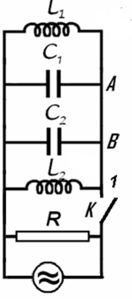
Let’s consider the electric circuit in the figure, for which L1=10mH , L2=20mH , C1=10nF , C2=5nF and R=100kΩ . The switch K being closed the circuit is coupled with a source of alternating current. The current furnished by the source has constant intensity while the frequency of the current may be varied.
a. Find the ratio of frequency fm for which the active power in circuit has the maximum value Pm and the frequency difference Δf=f+−f− of the frequencies f+ and f− for which the active power in the circuit is half of the maximum power Pm .
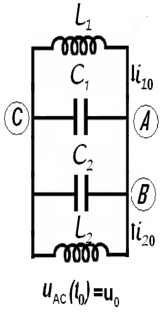
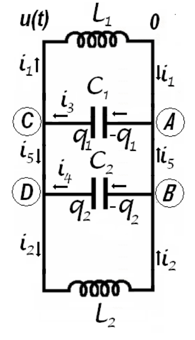
The switch K is now open. In the moment t0 immediately after the switch is open the intensities of the currents in the coils L1 and i01=0,1A and i02=0,2AL1 (the currents flow as in the figure); at the same moment, the potential difference on the capacitor with capacity C1 is u0=40V :
b. Calculate the frequency of electromagnetic oscillation in L1C1C2L2 circuit;
c. Determine the intensity of the electric current in the AB conductor;
d. Calculate the amplitude of the oscillation of the intensity of electric current in the coil L1 .
Neglect the mutual induction of the coils, and the electric resistance of the conductors. Neglect the fast transition phenomena occurring when the switch is closed or opened.
Решение
a.
As is very well known in the study of AC circuits using the formalism of complex numbers, a complex inductive reactance XˉL=Lωj, (j=−1) is attached to the inductance L - part of a circuit supplied with an alternative current having the pulsation ω. Similar, a complex capacitive reactance XˉC=−j/(Cω) is attached to the capacity C. A parallel circuit will be characterized by his complex admittance Yˉ. The admittance of the AC circuit represented in the figure is
The circuit behave as if has a parallel equivalent capacity C
C=C1+C2(2.2)
and a parallel equivalent inductance L
L1=L11+L21,L=L1+L2L1L2,(2.3)
The complex admittance of the circuit may be written as
Yˉ=R1+j(Cω−Lω1).(2.4)
and the complex impedance of the circuit will be
Zˉ=Yˉ1=(R1)2+(Cω−Lω1)2R1+j(Lω1−Cω).(2.5)
The impedance Z of the circuit, the inverse of the admittance of the circuit Y is the modulus of the complex impedance Zˉ
Z=∣Zˉ∣=(R1)2+(Cω−Lω1)21=Y1.(2.6)
The constant current source supplying the circuit furnish a current having a momentary value i(t)
i=I2sinωt,(2.7)
where I is the effective intensity (constant), of the current and ω is the current pulsation (that can vary). The potential difference at the jacks of the circuit has the momentary value u(t)
u=U2sin(ωt+φ).(2.8)
where U is the effective value of the tension and φ is the phase difference between tension and current.
The effective values of the current and tension obey the relation
U=IZ.(2.9)
The active power in the circuit is
P=RU2=RZ2I2,(2.10)
Because as in the enounce,
I=constant,R=constant.(2.11)
the maximal active power is realized for the maximum value of the impedance that is the minimal value of the admittance. The admittance
Y=(R1)2+(Cω−Lω1)2.(2.12)
has– as function of the pulsation ω - an „the smallest value”
Ymin=R1(2.13)
for the pulsation
ωm=LC1,(2.14)
In this case
Cω−Lω1=0.(2.15)
So, the minimal active power in the circuit has the value
Pm=RI2.(2.16)
and occurs in the situation of alternative current furnished by the source at the frequency fm
fm=2πωm=2πCL1.(2.17)
To ensure that the active power is half of the maximum power it is necessary that
P=21Pm,RZ2I2=21RI2,R22=Z21=Y2.(2.18)
That is
R22=R21+(Cω−Lω1)2,±R1=Cω−Lω1.(2.19)
The pulsation of the current ensuring an active power at half of the maximum power must satisfy one of the equations
ω2±RCω−LC1=0.(2.20)
The two second degree equation may furnish the four solutions
ω=±2RC1±21(RC1)2+LC4.(2.21)
Because the pulsation is every time positive, and because
(RC1)2+LC4>RC1,(2.22)
the only two valid solutions are
ω±=21(RC1)2+LC4±2RC1.(2.23)
It exist two frequencies f±=ω±/(2π) allowing to obtain in the circuit an active power representing half of the maximum power.
the bandwidth of the circuit – the frequency interval around the resonance frequency having at the ends a signal representing 1/2 from the resonance signal. At the ends of the bandwidth the active power reduces at the half of his value at the resonance. The asked ratio is
The (2.26) relation is the answer at the question a.
b.
The fact that immediately after the source is detached it is a current in the coils, allow as to admit that currents dependents on time will continue to flow through the coils.
Figure 2.1
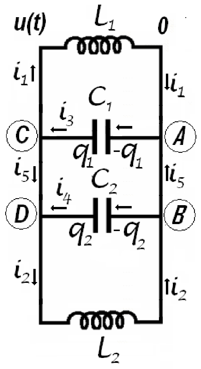
The capacitors will be charged with charges variable in time. The variation of the charges of the capacitors will results in currents flowing through the conductors linking the capacitors in the circuit. The momentary tension on the jacks of the coils and capacitors – identical for all elements in circuit – is also dependent on time. Let’s admit that the electrical potential of the points C and D is u(t) and the potential of the points A and B is zero. If through the inductance L1 passes the variable current having the momentary value i1(t), the relation between the current and potentials is
u−L1dtdi1=0,(2.28)
The current passing through the second inductance i2(t) has the expression,
u−L2dtdi2=0.(2.29)
If on the positive plate of the capacitor having the capacity C1 is stocked the charge q1(t), then at the jacks of the capacitor the electrical tension is u(t) and
q1=C1u,(2.30)
Deriving this relation it results
dtdq1=C1dtdu,(2.31)
But
dtdq1=−i3,(2.32)
because the electrical current appears because of the diminishing of the electrical charge on capacitor plate. Consequently
i3=−C1dtdu.(2.33)
Analogous, for the other capacitor,
i4=−C4dtdu.(2.34)
Considering all obtained results
dtdi1=L1u,dtdi2=L2u,(2.35)
respectively
dtdi3=−C1dt2d2u,dtdi4=C2dt2d2u.(2.36)
Denoting i5(t) the momentary intensity of the current flowing from point B to the point A, then the same momentary intensity has the current through the points C and D. For the point A the Kirchhoff rule of the currents gives
In the expression above, A, M, N and δ are constants that must be determined using initially conditions. It is remarkable that the currents through capacitors are sinusoidal but the currents through the coils are the sum of sinusoidal and constant currents. In the first moment
is valuable for any value of the argument α only if
A=C,B=D.(2.58)
Considering (2.58), from (2.56) it results
M+N=0,Aω(C1+C2)=−ωA(L11+L21).(2.59)
For the last equation it results that the circuit oscillate with the pulsation in the relation (2.44). Adding relations (2.55) and considering (2.54) and (2.59) results that
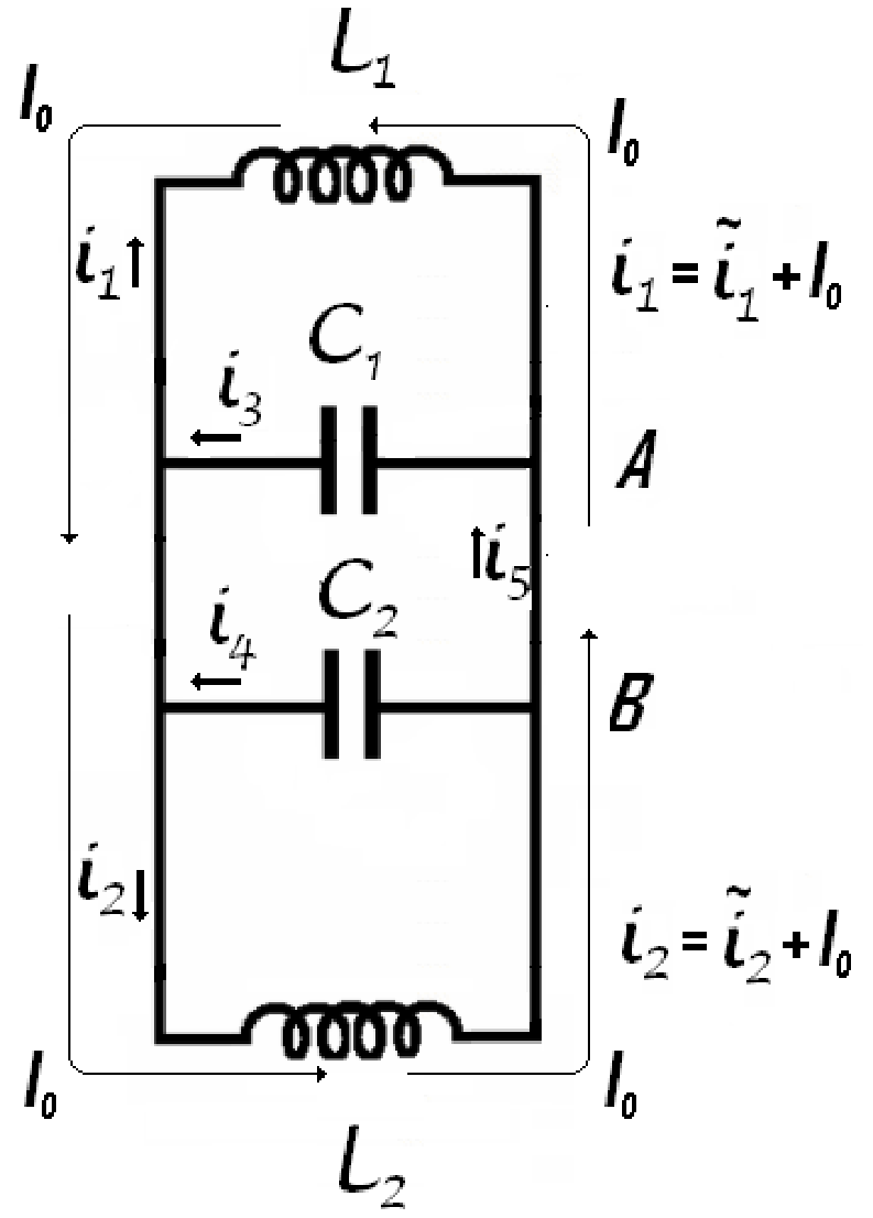
The currents through the coils are the superposition of sinusoidal currents having different amplitudes and a direct current passing only through the coils. This direct current has the constant value
I0=0.1A(2.69)
as in the figure 2.2.
The alternative currents through the coils has the expressions
Observation: the currents through the coils are the superposition of sinusoidal currents having different amplitudes and a direct current passing only through the coils.
For
Score
The direct current I0=0.1A
0.1
The alternative currents through the coils: i~1=(100426cos(105t+arctg(1/5)))A; i~2=(100226cos(105t+arctg(1/5)))A
0.2
The currents through the capacitors: i3=(−100426cos(105t+arctg(1/5)))A; i4=(−100226cos(105t+arctg(1/5)))A
0.2
i5=i3−i1
0.1
Final result: i5=[−100826cos(105t+arctg51)+0.1]A
0.2
II.d. — 0.3 points
For: the amplitude of the current through the inductance L1