IPhO 1992, Експеримент — Задача 1. Investigation of the Electric Breakdown of Air
Experimental problem 1 · Investigation of the Electric Breakdown of Air · 10 т.
Experimental competition instructions and source scope
XXIII INTERNATIONAL PHYSICS OLYMPIAD — HELSINKI, ESPOO
EXPERIMENTAL COMPETITION — July 9th 1992
Available time: hours.
READ THIS FIRST
After two and a half hours you must stop carrying out your first experiment and go to another room for the second experiment.
Instructions:
- Use no other pen than the one allotted by the organizers
- Do not use the same paper for different problems.
- Use only the marked side of the paper
- Write at the top of each and every page: the number of the problem; the number of the page per problem, starting by number 1; the total number of pages per problem. Example: 1 1/4; 1 2/4; 1 3/4; 1 4/4
- Mark the graph papers with your identification.
Editorial source note: this edition contains experiment 1 only. The archival booklet includes its official solution and retrospective grading commentary on pages 4–12. The separately catalogued solution PDF reproduces the same twelve page images. No completed measurement table or experimental result plot is supplied; the instructions require participants to produce them.
Условие
In this experimental problem the electric breakdown of air is to be studied by means of high voltages generated by piezoelectric material.
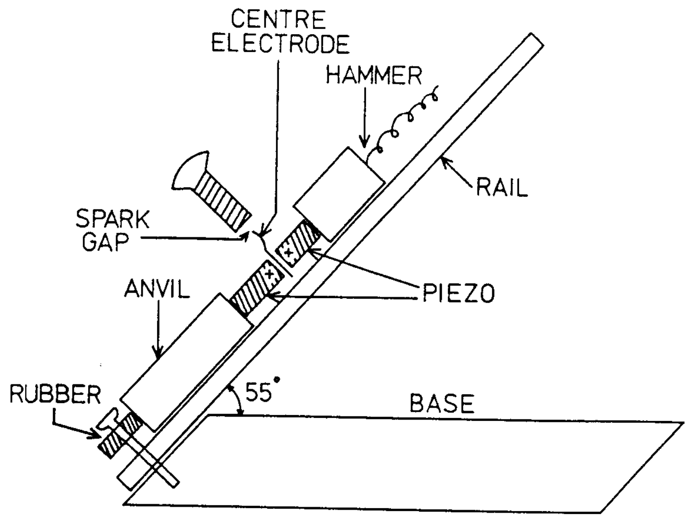
The experimental apparatus consists of an inclined slide (see figure) on which a hammer of mass can slide down a guide rail. The sliding hammer then hits an assembly of two cylinders of piezoelectric material and compresses them. Compression of the piezoelectric material causes electric charging of the ends of the cylinders. The generated voltage is conducted to an adjustable spark gap. If the gap is small enough there will be a spark across the gap which can be seen by the naked eye. However, if the voltage is too small, there will be no spark. The smallest voltage that produces a spark over a given gap is called the breakdown voltage of the gap.
Instructions
- determine the breakdown voltage as a function of the gap width;
- estimate the errors in the results, and discuss the nature of the various errors.
In your report,
- explain your experimental procedure;
- explain how you have overcome the experimental difficulties in performing the measurements;
- discuss the general validity of this result in other situations in which electrical breakdown of air occurs;
- write down the serial number on your piezoelectric assembly so that your results can be checked.
Discussion of the theory for a piezoelectric cylinder
The full theory of a piezoelectric is not required in this experiment. The following approximate analysis is sufficient.
The piezoelectric cylinder can be modelled as a combination of a mechanical spring and an electric capacitor. The two ends of the cylinder act as the plates of the capacitor. When the spring is compressed, the compressing movement causes electric charge to move from one plate of the capacitor to the other plate, causing a voltage to appear across the capacitor. The quantity of charge moved is proportional to the amount of compression. The process is reversible: when the compressing force is released and the material resumes its original shape, an opposite movement of charge takes place. Consider the following sequence of events with a piezoelectric cylinder of capacitance : 1) a force is applied on the cylinder; 2) the two ends of the cylinder are momentarily short circuited; and 3) the force is removed. In (1), a charge is transferred and the voltage appears across the cylinder. In (2), the voltage drops to zero, . In (3), a smaller voltage is generated of opposite sign to the original voltage.
The capacitance of the piezoelectric cylinder is denoted by . When an initially uncharged and unstressed piezoelectric cylinder is compressed so that mechanical work is done by the compressing force, then energy is transformed into electrical energy and stored in the capacitor (capacitance ). The value of the constant depends on the piezoelectric material. The manufacturer of the piezoelectric cylinders used in this experiment reports that
Performing the experiment
The piezoelectric assembly supplied has been made so that compression causes a positive charge to appear in the ends of the piezoelectric cylinders which are marked + in the figure. The + ends are connected to each other and to an electrode in the centre of the assembly which acts as one terminal of the spark gap.
The apparatus is arranged so that the hammer makes electrical contact with the upper end of the top piezoelectric cylinder, thus connecting the piezoelectric material with the metal rail.
There is a larger mass which acts as an anvil below the piezoelectric assembly. The compressing force is generated by the combined action of the hammer and the anvil. The anvil is supported on a cushion of foam rubber so that no sudden impact force is transmitted from the anvil to the base of the equipment. The anvil provides an electrical connection between the lower end of the bottom piezoelectric cylinder and the rail. There is a copper wire connected from the rail to an adjusting screw which serves as the other terminal of the spark gap.
There is a limiter on the rail which prevents the hammer from exceeding a height of approximately 10 cm. Do not attempt to bypass this limiter. Contact the invigilator if you are unable to observe any sparks at all.
There are two methods for observing the sparks:
- Visual observation of the spark. If this method is used, then it is necessary to make the electrical connection between the adjusting screw and the sliding rail.
- Feeling the spark with your finger. If this method is used, disconnect the grounding wire and instead, touch one finger to the screw and another finger to the metal rail. The spark current will go through your hand and you will be able to feel whether there is a spark or not.
You can use whichever method you prefer, or both methods if you wish.
In addition to the apparatus discussed above, a triangular ruler/protractor, a small screw driver, and some sheets of graph paper are provided.
Data for the experimental apparatus
| Quantity | Value |
|---|---|
| Acceleration due to gravity | |
| Capacitance of one piezoelectric cylinder | |
| Mass of the hammer | |
| Combined mass of the piezoelectric assembly and anvil | |
| Angle of the slide rail with respect to the horizontal direction | |
| Pitch of the thread on the screw used for adjusting the spark gap |
Notes
- The capacitor equivalent of the piezoelectric cylinder, , has a very low leakage current, thus it can keep a charge for a long time. Bear this fact in mind when planning your experimental procedures.
- The electrical charge generated by the piezoelectric material is so small that it is not dangerous. The spark does not hurt but you can feel it!
- There is a small risk that the piezoelectric cylinders could shatter into pieces because of the repeated impacts. If this should happen, contact the organizers: there are spare cylinders available. In order to avoid breakages, make sure that the piezoelectric assembly rests properly on the rail and is pressed securely against the anvil before each impact. Suspend the hammer by the thread supplied before letting it slide, so that it will slide smoothly without jumping.
- The capacitance of the spark gap is so small that it need not be taken into account.
- The hammer and anvil are considered to be absolutely rigid bodies, so they are not compressed by the impact.
Решение
Official solution and retrospective grading commentary from the source booklet.
Modelling the physical reality
In many exercises and competition problems the participants are told exactly what to do: to neglect or not to neglect air resistance, friction, flexibility, or other such details. In contrast, this experimental problem is presented in an open form: the goal of the experiment is stated (=determination of the breakdown strength of room air) but the means for achieving this goal are left to the participants. This resembles the situation in real physical research work: something should be measured but there are no set rules about how to proceed with the measurements. If the researcher ignores essential interactions then his/her results are simply wrong and there is no such excuse as ‘but I decided to ignore air resistance’. An essential part of the present problem consists of the modelling of the experimental situation and in deciding what interactions to ignore and what to take into account. The simple and natural rule is: take into account all those interactions whose effects exceed or are comparable to the general level of errors in the measurements (provided that these interactions can be modelled). On the other hand, it is not necessary to evaluate such quantities which don’t affect the results: the true coefficient of friction is not needed, one can use the apparent coefficient and save some error-prone trigonometric calculations (see below).
The following potentially harmful interactions may be identified:
1. Air resistance. The hammer moves through an air column of length less than 13 cm. The mass of this air column is less than one thousandth of the mass of the hammer. Thus also the energy deposited by the hammer to the turbulent movement of the displaced air is less than one thousandth of the energy of the hammer. This order-of-magnitude estimation indicates that the turbulent air drag can be neglected. Also, the general physical experience should indicate that for this kind of motion the viscous drag is smaller than the turbulent drag (=the Reynolds number is greater than unity). Thus also the viscous drag can be neglected. Because the influence of air resistance is so small, we don’t expect that air resistance is discussed by the participants.
2. Friction. Some participants felt that because the coefficient of friction was not given it was correct to ignore the friction. A great majority understood the problem in the same spirit as it was given: the friction is essential and the coefficient of friction can be estimated by tilting the device and by observing the motion of the hammer on the tilted rail.
The ideal solution would be as follows: tilt the rail to a selected angle and keep it fixed. Put the hammer on the rail and push it slightly so that it starts to move. If the hammer continues to slide with approximately constant velocity, then the tilting angle is correct for computing the apparent coefficient of dynamic friction (see later). If the hammer stops, then the slope is too small. And if the hammer accelerates down the slope, then the slope is too steep.
Such solutions were also accepted where the coefficient of static friction was determined and used instead of the dynamic friction. It can be estimated simply by tilting the rail until the hammer starts to move. In the present case, the difference between static and dynamic friction is relatively small.
3. The finite mass of the anvil. In the problem definition it was stressed that no sudden forces are transmitted from the anvil to the main body of the equipment. Thus the anvil, piezo, and hammer must be considered ‘free-flying’ during the impact and the total impulse of these three bodies is conserved throughout the impact. One part of the kinetic energy of the hammer goes for the compression of the piezo but another part remains as the kinetic energy of these three bodies which are moving together as one piece during the time of strongest compression.
4. Deformations of the hammer and the anvil. Although the anvil is of steel it is somewhat deformable: the impact sends a compression wave travelling down the anvil, and there is some energy in this wave. On one hand, this amount of energy is quite small. On the other hand, it would be practically impossible to estimate this energy during the competition. Thus we included the instruction that the anvil should be considered absolutely rigid. The same applies even more to the hammer which is shorter and thus less resilient.
5. Residual voltage of the piezo condenser. After one impact has been made, the charging status of the piezo condenser is unknown. There may be negative charge which has been formed in the piezo during the decrease of compression after the spark has short-circuited the capacitor. Such a charge would reduce the largest positive charge generated by the next impact and would thus tend to prevent another spark from appearing. Thus it is essential that the piezo is discharged by short-circuiting between the impacts. This is most easily done by short-circuiting the spark gap with the provided screw-driver.
It is important to understand that the piezo may acquire a charge even if no spark is observed. This is due to weak corona discharges which are diffuse and not visible in daylight.
Calculations
We denote by the length of the sliding path of the hammer and by the angle between the sliding path and the horizontal direction. When the hammer travels the length , it descends by the amount in the gravitational field of earth. So it converts the gravitational energy
into mechanical energy.
The gravitational force is represented as the sum of two perpendicular forces:
where is parallel to the sliding path and is normal to it:
The frictional force is parallel to and
where is the apparent coefficient of dynamic friction. Energy loss by friction is
For determining the apparent coefficient of friction one has to determine an angle so that when the sliding path has the sloping angle , the hammer slides without losing or gaining energy. Then frictional energy loss equals gravitational energy gain:
This gives .
Energy of hammer before impact is thus
where is the velocity of the hammer when the impact is about to start. Conservation of impulse gives the velocity of the combination hammer + piezo + anvil when there is maximum compression, i.e. when all three move as one piece:
At maximum compression there is no relative movement of the three bodies with respect to each other. Thus the kinetic energy of the three bodies is obtained from the common movement:
Kinetic energy used for compressing the piezo is the difference of the kinetic energies before impact and at maximum compression:
The fraction of this energy is used for generating the electrical energy:
The voltage is solved from the preceding equation:
Here is the combined capacitance of the two piezo capacitors in parallel: pF.
In the problem, the coefficient is reported without an error estimate (again, typical for a real experimental situation). It is an empirical quantity. It would be incorrect to assume that it is an exact value. One could assume that or .
Editorial source note: equations (1) and (2) print vector arrows on both sides although the scalar factors specify component magnitudes. The printed vector notation is retained.
Measurements and presentation of results
The gap width should be determined by using the electrode screw as a micrometer. It is natural to do the measurements with one turn intervals.
The object of this work is to investigate electrical breakdown. As the measurements will show, there is considerable scatter or randomness in the phenomenon. If only some ‘best’ or mean values are reported, then an important part of information is left out. One should report the original data in a suitable format, either as a table or as a diagram.
The measurements are best organized so that one gap setting at a time is investigated. One should try several falling heights, so that for the lowest heights, no sparks are seen, and for the highest, all trials produce a spark. For each height, several trials should be made.
It might be good to record all results immediately in graphical form in a diagram where abscissa axis shows the gap width and the ordinate axis shows , the sliding length of the hammer. The result of each trial should be recorded in this diagram as a mark, e.g. so that a mark ‘+’ is drawn if there is a spark, and a mark ‘0’ is drawn if there is no spark. The set of marks corresponding to same values and should be drawn as a cluster of marks near each other. This diagram would show the randomness of the phenomenon. Then one should find the representative values of for breakdown from this diagram (see next paragraph). It would be enough to do the conversion to voltage only for these representative values, not for all observations.
There is also the question of what is meant with the concept ‘breakdown voltage’. The wording of the problem defines it as ‘the smallest voltage that produces a spark over a given gap’. It would be better to interpret this so that breakdown voltage is ‘the smallest voltage where the majority of experiments produce a spark’. Such voltage values can be visually determined from the figure.
Another diagram should be drawn, showing how the voltage values depend on the gap length. When the task is to investigate the voltage it is not enough to show a diagram of falling heights.
Some participants understood the problem so that a coefficient would be needed which would give the ratio of breakdown voltage and gap length, i.e. express the breakdown voltage in ‘Volts/millimeters’. Because spark formation is quite nonlinear such a coefficient is not very meaningful and we ignored that part of computed results. However, some competitors also fitted a straight line or a curve to their results so that this line or curve went through the origin. Offering such a diagram as part of the results was considered an outright error because it would communicate to the reader of a research report an interpretation of the data which is unfounded by the observations and contradicts known theory.
Analysis of errors
There was the question about general validity of results. One should mention that spark formation depends strongly on humidity and on electrode shape, and also on the duration of the high tension pulse and on air pressure. Thus the results are without any general validity whatsoever. This should be mentioned in the report.
A complete analysis of errors should consider systematic and random errors separately. The errors in , , , , and are systematic, they are same for all individual measurements made with one equipment. Thus the random errors are small (due to and and variation of ), and the relative accuracy of the readings is rather high, certainly better than 10 %. On the other hand, considerable scatter is seen in the results. Thus one might conclude that most part of the scatter of results must be due to the random nature of the fast spark process itself (possibly due to the presence or non-presence of suitable free ions or aerosol particles for initiating the discharge).
Grading
Experimental results might be graded by the quality of the obtained results. In this case it was not possible because of the following reasons:
- The conditions in the room could not be fully controlled. Both humidity and illumination levels varied throughout the day, causing correct results to change and making the observation of sparks more difficult in the brighter light of noon time.
- There were probably some individual differences between the different piezo devices. Also, it was possible that an invisible crack was formed in the piezo during one experimental session so that it influenced the next competitor without his/her own fault. Thus all results of different numerical values were accepted if their order of magnitude was reasonable.
The schedule for grading the experimental problems was extremely tight. Thus it was decided to use a fixed grading table. The entries and their values were as follows:
Acceptable results (3 points -1 -1/2)
This required that there are in table form or graph form the results (voltage vs. gap) and that these results are reasonable: we required that the correct equation for energy of a capacitor had been used etc. Also it was required that the values are not meaningless. We did not consider acceptable such results which were smaller than a few hundreds of volts or more than 1 MV!
From these 3 points we subtracted one point if a line or curve had been fitted to the points so that this curve was forced to run straight to origin, implying that voltage is inherently proportional to gap length. We regarded this as a non-physical assumption which is seriously distorting the results.
If the competitor did not know the unit pF we deducted half a point from those 3 points. Even if this unit is not normally used in schools in some countries, we regard it as common physical knowledge which should be mastered. And assuming that nano is known, pico cannot mean the same. Thus one can logically conclude that is the only probable choice because would lead to suspiciously high voltages, to hundreds of kilovolts.
Friction correction (1 point)
This credit was given if the (apparent) friction coefficient was estimated empirically by tilting the device. We didn’t require the use of the sliding method for determining dynamic friction, as described earlier in this report. This credit was not given if the friction coefficient was guessed or specifically ignored.
Center-of-mass energy (2 points)
If the factor was present, two points were given.
Error estimate of K (1/2 point)
In reality the value given for is probably the largest single cause for error of the results. In good real work it would be necessary to calibrate the equipment when the error of is not given. Now it was not possible to calibrate. Thus the error of could not be properly estimated. However, we required that is recognized as a source of error and that the uncertainty of is assumed to be at least 0.05 units. Fulfilling this requirement earned half a point of credit.
A similar situation is often encountered in real life: one must use a value but there is no easy method of getting a reliable error estimate for it.
Randomness indicated (1/2 point)
The sparking itself is a random process, and the results should indicate some randomness. If all this randomness had been removed in the preliminary treatment of data or if only one set of experiments was made, and randomness was not explained in the report, then we considered that one important result was missing. If randomness was somehow indicated in the results, half a point was given.
General validity (1/2 + 1/2 points)
There is the question about the general validity of the results. The two most important conditions which cause that the results have no general validity are the shape of electrodes and the environmental variables (humidity, air pressure, temperature etc.). It was required that both were mentioned. However, it was considered sufficient if air pressure was mentioned in stead of humidity.
Short circuiting (1 point)
One point was given if it was mentioned in the report that the piezo capacitor was short-circuited between individual trials. A few reports revealed that this was not fully understood: either the short circuiting was only done after a spark, or only after no spark, or it was attempted after the hammer had been raised. However, the full point was given to all who mentioned this detail even if there was some misunderstanding.
Micrometric use of the screw (1 point)
In order to get good results, it is essential to measure the gap by using the screw as a micrometer. If such a technique was mentioned in the report or if it was evident (=if the distance values were multiples of 0.8 mm) then one point was given for this experimental skill. Most competitors received this credit.
Special credits (1/2 + 1/2 points)
A few competitors remarked that there is a depression in the tip of the screw which makes the distance readings inaccurate or biased. Such a remark was awarded an extra half point. The full score of 10 points could be obtained without this half-point.
In some cases the rigid scheme does not do full justice. E.g., if there is a good table of dropping distance vs. gap, this does not merit our ‘Acceptable results’ (3) points. Also, sometimes there is a feel of quality in the work which can’t be included in any fixed grading scheme. In such cases an extra bonus of 1/2 points was given. The full score of 10 points is possible without this half-point.
Remarks
Our preliminary experiments clearly indicated that dirt affects the apparent coefficient of friction. Handling the hammer by hands leaves some grease on the cylindrical sliding surface, this grease accumulates dust, and the apparent coefficient of friction is increased. In order to obtain stable results one should clean the hammer and the sliding rail every now and then. For this purpose, a paper towel was included in the equipment which was made available for this problem. But hardly any competitor used the towel! This aspect was ignored in the grading.
The rail was made of anodized aluminium because it gave a more repeatable friction than uncoated aluminium. The anodized coating is, however, isolating. Thus we had to make a few scratches in the coating below the anvil and the hammer so that the electric current could penetrate the coating without a large voltage drop.
It is quite tiresome to drop the hammer many times from a precisely determined falling height if one has to read the height each time on the provided scale. For this reason, a clothes-peg was supplied as part of the equipment. It was intended to be used as an adjustable stopper so that one lifts the hammer up against the stopper and lets it fall from this position. This procedure would make the repetition of measurements quick and easy. However, only a few of the participants used the clothes-peg in this way. Many of them used the clothes-peg as a pincer for gripping the tail of the hammer although it seemed to make the work harder than without.
The most important concern in constructing, operating and maintaining the piezo impact device is: how to make sure that the impact on the piezo happens uniformly so that the hammer touches all of the surface of the piezo end. This requirement is very strict, the maximum allowable skewness is at most a few . The requirement was probably not met by some of the units used in the competition. This can be suspected because ten piezo devices were broken during the competition. — Another reason for breaking can be that the hammer was dropped carelessly, so that it bounced on the rails and hit the piezo in a skewed position. When observing the competitors during the competition one could see that quite a number of them simply did not follow the advice of letting the hammer fall smoothly so that it does not bounce.
Оригинал в Архива: 23rd_IPhO_1992_exp_problem_1.pdf · официални решения: exp1_sol.pdf