IPhO 1994, Експеримент — Задача 2. Black Box
XXV International Physics Olympiad — Beijing, People’s Republic of China — Practical competition, July15,1994 · 15 юли 1994 г. · 10 т.
Внимание: Бележка към темата
The complete archived booklet contains two whole experiments, including Black Box, which the archive task listing omits. Experiments are shown here using original pages22–36. The round total20 is the sum of the native10-point marking schemes. Archived worked solutions have no established official authorship. Native differences/errors are retained: polarizerA/P1 labels, the linearity prose ratio versus the displayed formula, differing Brewster-angle uncertainties, low-frequency impedance/inductance wording, high-frequency Z_L approximately0 statement and original uncertainty values. Referenced separate oscilloscope/frequency-generator panel illustrations and plotting papers are absent from the obtained booklet; no missing illustrations or measurements are invented.
Practical competition — July15,1994 — Time available:2.5hours
- Use only the ball pen provided.
- Your graphs should be drawn on the answer sheets attached to the problem.
- Write your solution on the marked side of the paper only.
- The draft papers are provided for doing numerical calculations and draft drawings.
- Write at the top of every page:
- The number of the problem
- The number of the page of your report in each problem
- The total number of pages in your report to the problem
- Your name and code number
Условие
Given a black box with two similar terminals. There are no more than three passive elements inside the black box. Find the values of elements in the equivalent circuit between the terminals. This box is not allowed to be opened.
Experimental Apparatus
- Double channel oscilloscope with a panel illustration, showing the name and function of each knob.
- Audio frequency signal generator with a panel illustration, showing the name and function of each knob.
- Resistance box with a fixed value of ().
- Several connecting wires.
- For the coaxial cables, the wire in black color at the terminal is grounded.
- Log-log paper, semi-log paper, and millimeter paper are provided for use if necessary.
Note: The knobs, which were not shown on the panel illustration of the “signal generator” and “oscilloscope”, have been set to the correct positions. It should not be touched by the student.
Experimental Requirements
1) Draw the circuit diagram in your experiment. [2 т.]
2) Show your measured data and the calculated results in the form of tables. Plot the experimental curves with the obtained results on the coordinate charts provided (indicate the title of the diagram and the titles and scale units of the coordinate axes). [2 т.]
3) Given the equivalent circuit of the black box, and the names of the elements with their values in the equivalent circuit (write down the calculation formulas). [6 т.]
Instructions
- Do your experiment in the frequency range between and .
- The output voltage of the signal generator should be less than (peak-to-peak). Set the “Out Attenuation” switch to “20” db position and it should not be changed.
- On connecting the wires, be careful to manage the wiring so as to minimize the interference from the electric mains.
Instruction for Using XD2 Type Frequency Generator
- Set the “Out Attenuation” to “20” db position and it should not be changed.
- Set the “Damping Switch” to “Fast” position.
- The indication of the voltmeter of the signal generator is the relative value, but not the true value of the output.
- Neglect the error of the frequency readings.
Note: For XD22 Type Audio Frequency generator, there is no “Damping Switch”, and the “output” switch should be set to the sine “~” position.
Instruction for Using SS-5702 Type Oscilloscope
- Keep the “V mode” switch in “Dual” position.
- The “Volts/div” (black) and the “variable control” (red) vary the gain of the vertical amplifier, and when the “variable control” (red) is in the fully clockwise position, the black setting are calibrated.
- The “Times/div” (Black) varies the horizontal sweep rate from to , and they are calibrated when the “variable control” (red) is in the fully clockwise CAL position.
- The “Trigging Source” (Trigging sweep signal) is used to select the trigging signal channel and the “level” control is used to adjust the amplitude of the trigging signal.
- Measuring accuracy: .
Instruction for Using “Resistance Box”
The resistance of the “Resistance Box” has been set to a value of , and it should not be changed.
Решение
1)
The circuit diagram is shown in Fig. 1.
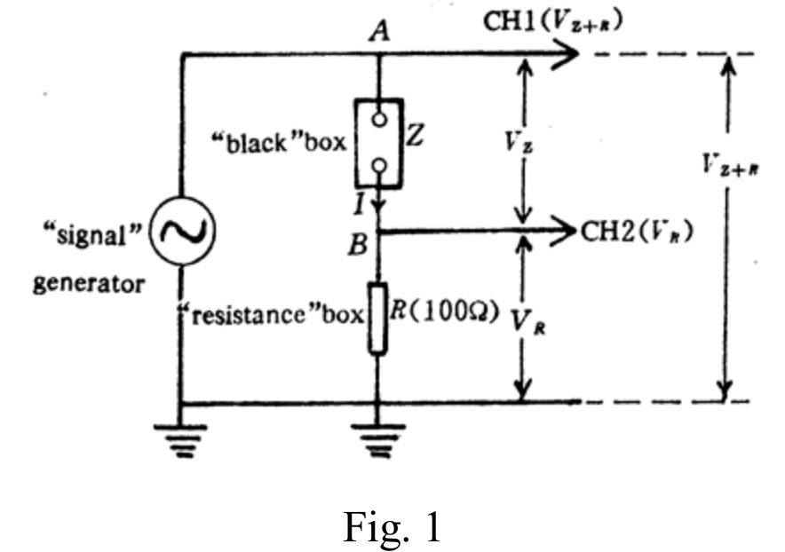
We have the relation:
2)
Measure the values of and at various frequencies , the measured data and calculated value of are shown in table 1. The - curve is plotted in Fig. 2.
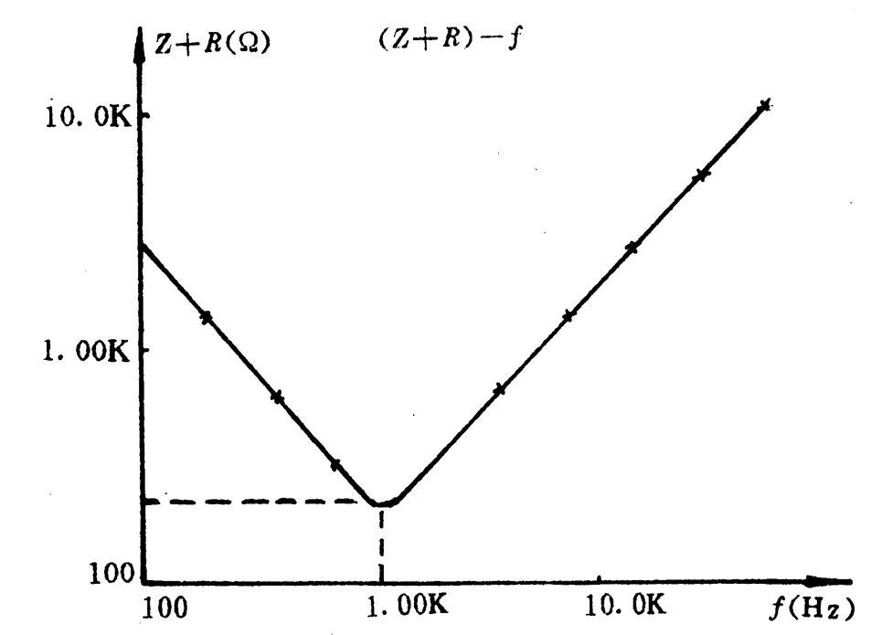
Table 1. The magnitude of impedance verus frequency
| () | () | () | () |
|---|---|---|---|
| 0.100 | 0.600 | 22.0 | 2.73 |
| 0.200 | 0.600 | 45.0 | 1.33 |
| 0.400 | 0.600 | 94.0 | 0.638 |
| 0.700 | 0.300 | 92.0 | 0.326 |
| 0.900 | 0.300 | 121 | 0.248 |
| 1.00 | 0.300 | 136 | 0.220 |
| 1.10 | 0.300 | 140 | 0.214 |
| 1.16 | 0.300 | 141 | 0.213 |
| 1.25 | 0.300 | 140 | 0.214 |
| 1.50 | 0.300 | 120 | 0.250 |
| 2.00 | 0.300 | 88.0 | 0.341 |
| 4.00 | 0.300 | 78.0 | 0.769 |
| 8.00 | 0.600 | 38.0 | 1.58 |
| 15.0 | 0.600 | 20.0 | 3.00 |
| 30.0 | 0.600 | 10.0 | 6.00 |
| 50.0 | 0.600 | 6.0 | 10.0 |
From table 1 and Fig. 2, we got the conclusions:
- Current resonance (minimum of ) occurs at .
- , , . The impedance of the “black box” at low frequency is dominated by a inductance.
- , , . The impedance of the “black box” at high frequency is dominated by a inductance.
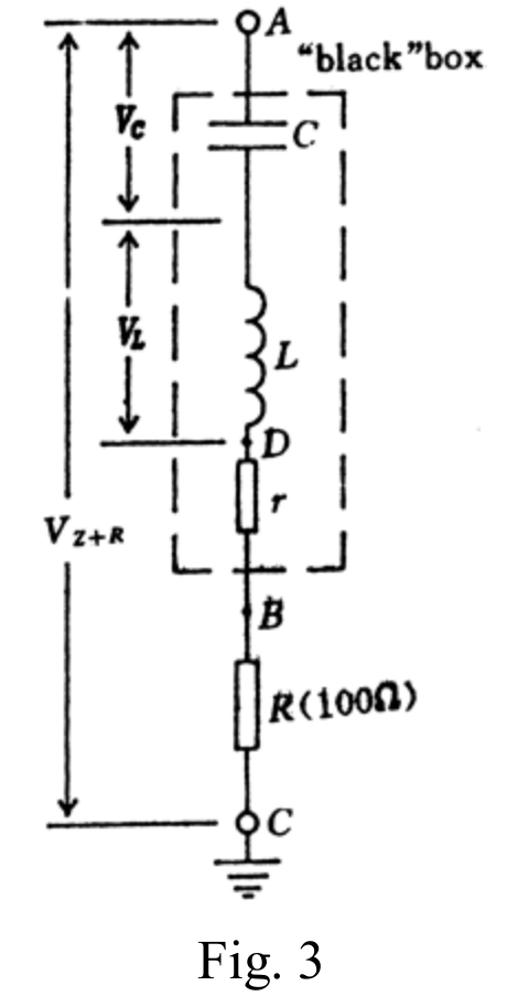
- Equivalent circuit of the “black box”: , and connected in series shown in Fig. 3.
3) — Determination of the values of r, L and C
(a)
At resonance frequency
Then
From table 1, , it is given , so the equivalent resistance in Fig. 3 is equal .
(b)
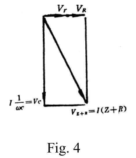
At low frequency, in Fig. 3. So the circuit could be considered as a series RC circuit.
From phasor diagram, Fig. 4,
Since at , can be neglected with respect to , so
(c)
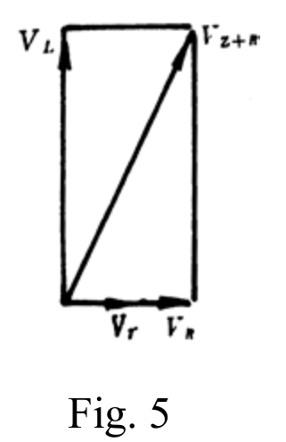
At high frequency, in Fig. 3. So the circuit could be considered as a series RL circuit.
From phasor diagram, Fig. 5,
Since at , can be neglected with respect to , so
Error estimation:
It is given, precision of the resistance box reading , precision of the voltmeter reading .
- Resistance : at resonance frequency
- Capacitance C: (Neglect the error of the frequency reading)
The approximation will introduce a percentage error .
- Inductance L: Similar to the results of capacitance C, but the percentage error introduced by the approximation is much small () and thus negligible.
Grading Scheme (10 points maximum)
- Measuring circuit is correct as shown in Fig. (a) — 2.0 point.
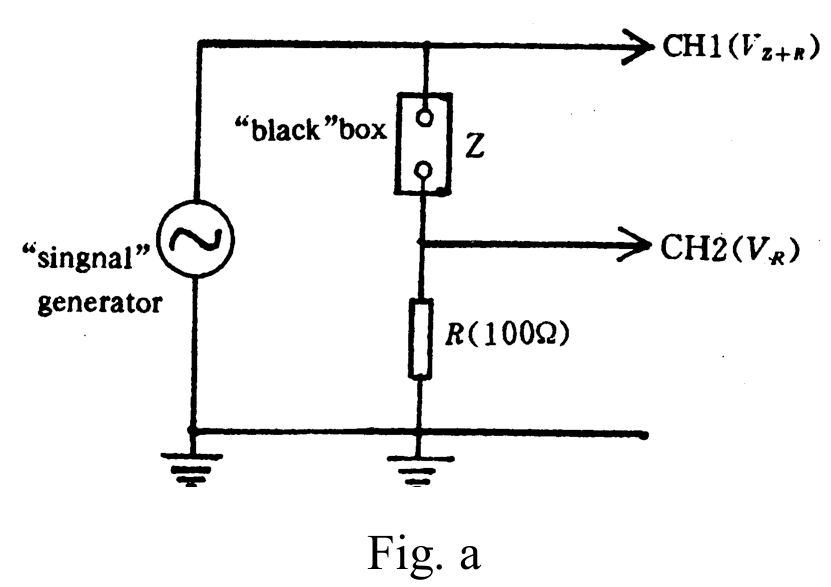
Correct data table and figure to show the characteristic of the black box — 2.0 points.
The equivalent circuit of the black box, and the names of the elements with their values in the equivalent circuit are correct — total 6.0 points.
(a) R, L and C are connected in series — 1.5 point. (L and C are connected in series — 1.0 point.)
(b) Correct value (error less than 15%) for each element — 0.5 point (×3).
(error between 15% and 30% 0.3)
(error between 30% and 50% 0.1)
(c) Correct calculation formula for each element — 0.5 point (×3).
(d) Error estimate is reasonable for each element — 0.5 points (×3).
Оригинал в Архива: ipho94.pdf · решение от архива: ipho94.pdf