IPhO 1998, Експеримент — Задача 1. Part I. Magnetic shielding with eddy currents
29th International Physics Olympiad, Reykjavik, Iceland — Experimental competition · 6 юли 1998 г.
Read this first
Monday, July 6th, 1998
Time available: 5 hours
Read this first:
Use only the pen provided.
- Use only the front side of the answer sheets and paper.
- Use as little text as possible in your answers; express yourself primarily with equations, numbers and figures. Summarize your results on the answer sheets.
- Please indicate on all sheets the name of your team, your student number, the page number and the total number of pages.
- At the end of the exam please put your answer sheets, pages and graphs in numerical order and leave them on your table.
- Use of a calculator is allowed.
This set of problems consists of 6 pages.
Examination prepared at: University of Iceland, Department of Physics.
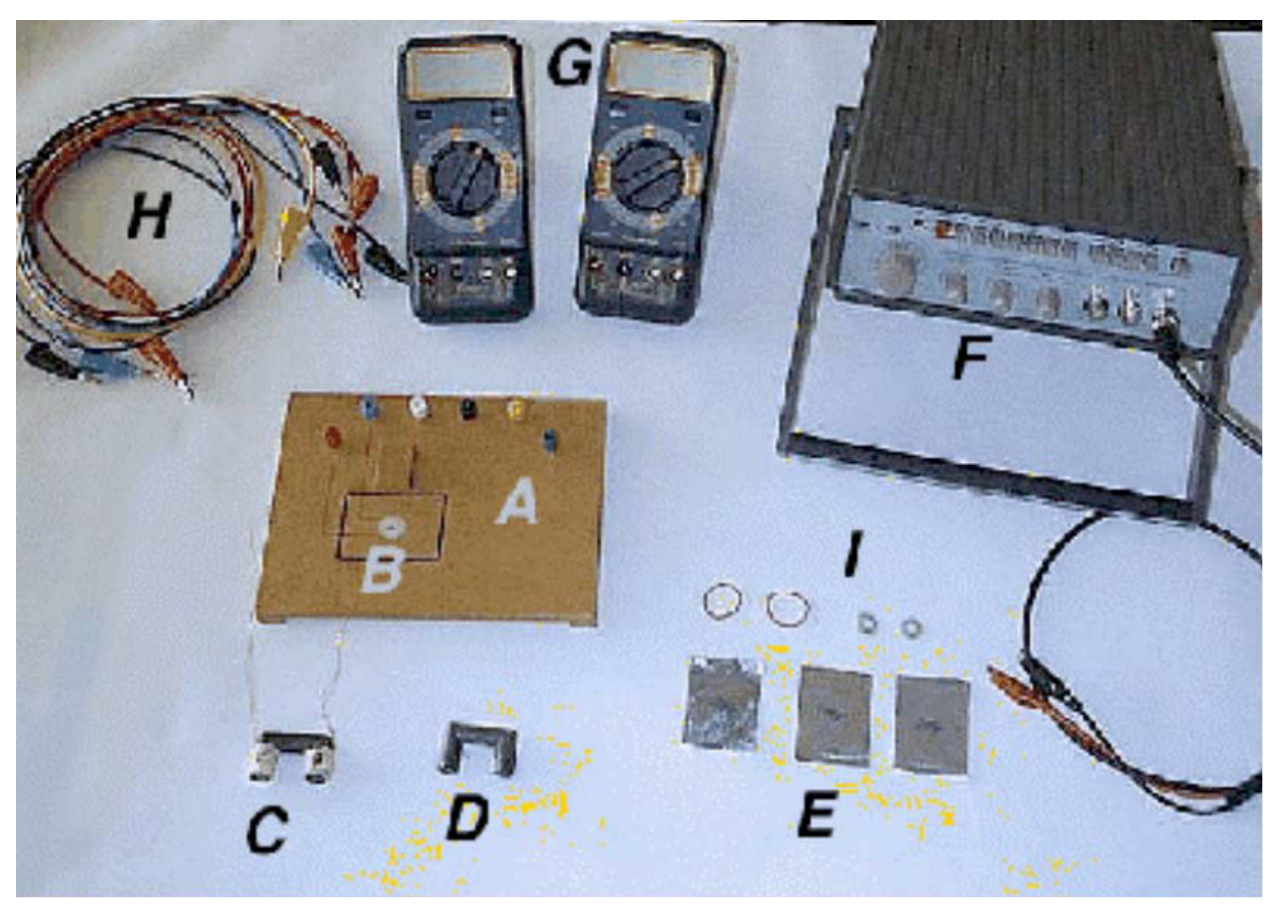
Instrumentation provided
Instrumentation provided:
A Platform with 6 banana jacks
B Pickup coil embedded into the platform
C Ferrite U-core with two coils marked ``A'' and ``B''
D Ferrite U-core without coils
E Aluminium foils of thicknesses: 50 µm, 100 µm and 200 µm
F Function generator with output leads
G Two multimeters
H Six leads with banana plugs
I Two rubber bands and two plastic spacers
Multimeters
The multimeters are two-terminal devices that in this experiment are used for measuring AC voltages, AC currents, frequency and resistance. In all cases one of the terminals is the one marked COM. For the voltage, frequency and resistance measurements the other terminal is the red one marked V-Ω. For current measurements the other terminal is the yellow one marked mA. With the central dial you select the meter function (V~ for AC voltage, A~ for AC current, Hz for frequency and Ω for resistance) and the measurement range. For the AC modes the measurement uncertainty is ± (4% of reading + 10 units of the last digit). To get accurate current measurements a change of range is recommended if the reading is less than 10% of full scale.
Function generator
To turn on the generator you press in the red button marked PWR. Select the 10 kHz range by pressing the button marked 10k, and select the sine waveform by pressing the second button from the right marked with a wave symbol. No other buttons should be selected. You can safely turn the amplitude knob fully clockwise. The frequency is selected with the large dial on the left. The dial reading multiplied by the range selection gives the output frequency. The frequency can be verified at any time with one of the multimeters. Use the output marked MAIN, which has 50 Ω internal resistance.
Ferrite cores
Handle the ferrite cores gently, they are brittle!! Ferrite is a ceramic magnetic material, with low electrical conductivity. Eddy current losses in the cores are therefore low.
Banana jacks
To connect a coil lead to a banana jack, you loosen the colored plastic nut, place the tinned end between the metal nut and plastic nut, and tighten it again.
Условие
Time-dependent magnetic fields induce eddy currents in conductors. The eddy currents in turn produce a counteracting magnetic field. In superconductors the induced eddy currents will expel the magnetic field completely from the interior of the conductor. Due to the finite conductivity of normal metals they are not as effective in shielding magnetic fields.
To describe the shielding effect of aluminium foils we will apply a phenomenological model
where is the magnetic field in the absence of foils. is the magnetic field beneath the foils, an attenuation constant, and the foil thickness.
Experiment
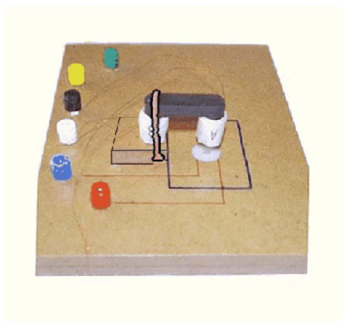
Put the ferrite core with the coils, with legs down, on the raised block such that coil A is directly above the pickup coil embedded in the platform, as shown in Figure 1. Secure the core on the block by stretching the rubber bands over the core and under the block recess.
1. Connect the leads for coils A and B to the jacks. Measure the resistance of all coils to make sure you have good connections. You should expect values of less than 10 Ω. Write your values in field 1 on the answer sheet.
2. Collect data to validate the model above and evaluate the attenuation constant for the aluminum foils (50 - 300 µm), for frequencies in the range of 5 - 20 kHz. Place the foils inside the square, above the pickup coil, and apply a sinusoidal voltage to coil A. Write your results in field 2 on the answer sheet.
3. Plot versus frequency, and write in field 3 on the answer sheet, an expression describing the function .
Решение
Внимание: Непълно решение
В архива няма официално решение на тази задача.
Оригинал в Архива: exp.pdf