IPhO 2000, Теория — Задача 2. Theoretical Problem 2
XXXI International Physics Olympiad ~ Theoretical Examination — Theoretical Problem 2 (DRAFT COPY)
Условие
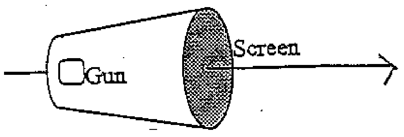
a) A cathode ray tube (CRT), consisting of an electron gun and a screen, is placed within a uniform constant magnetic field of magnitude B such that the magnetic field is parallel to the beam axis of the gun, as shown in figure 2.1.
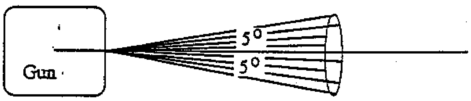
The electron beam emerges from the anode of the electron gun on the axis, but with a divergence of up to 5° from the axis, as illustrated in figure 2.2. In general a diffuse spot is produced on the screen, but for certain values of the magnetic field a sharply focused spot is obtained.
By considering the motion of an electron initially moving at an angle (where ) to the axis as it leaves the electron gun, and considering the components of its motion parallel and perpendicular to the axis, derive an expression for the charge to mass ratio for the electron in terms of the following quantities:
- the smallest magnetic field for which a focused spot is obtained,
- the accelerating potential difference across the electron gun (note that kV),
- , the distance between the anode and the screen.
Write your expression in the box provided in section 2a of the answer sheet.
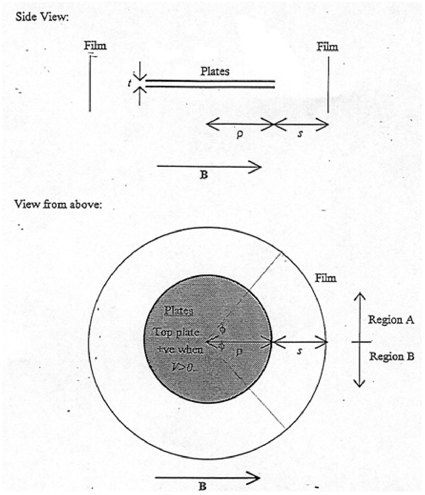
b) Consider another method of evaluating the charge to mass ratio of the electron. The arrangement is shown from a side view and in plan view (from above) in figure 2.3, with the direction of the magnetic field marked B. Within this uniform magnetic field B are placed two brass circular plates of radius which are separated by a very small distance . A potential difference is maintained between them. The plates are mutually parallel and co-axial, however their axis is perpendicular to the magnetic field. A photographic film covers the inside of the curved surface of a cylinder of radius , which is held co-axial with the plates. In other words, the film is at a radial distance from the edges of the plates. The entire arrangement is placed in vacuo. Note that is very much smaller than both and .
A point source of particles, which emits the particles uniformly in all directions with a range of velocities, is placed between the centres of the plates, and the same piece of film is exposed under three different conditions:
- firstly with , and ,
- secondly with , and , and
- thirdly with , and ;
where and are positive constants. Please note that the upper plate is positively charged when (negative when ), and that the magnetic field is in the direction defined by figure 2.5 when (in the opposite direction when ). For this part you may assume the gap is negligibly small.
Two regions of the film are labelled A and B on figure 2.3. After exposure and development, a sketch of one of these regions is given in figure 2.4. From which region was this piece taken (on your answer sheet write A or B)? Justify your answer by showing the directions of the forces acting on the electron.
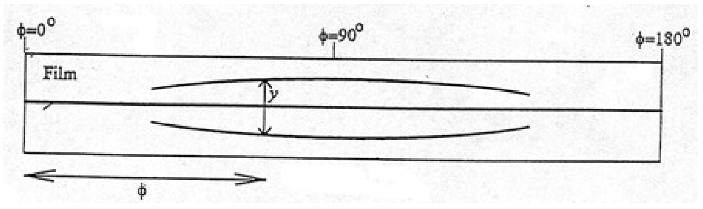
c) After exposure and development, a sketch of the film is given in figure 2.4. Measurements are made of the separation of the two outermost traces with a microscope, and this distance () is also indicated for one particular angle on figure 2.4. The results are given in the table below, the angle being defined in figure 2.3 as the angle between the magnetic field and a line joining the centre of the plates to the point on the film.
| Angle to field /degrees | 90 | 60 | 50 | 40 | 30 | 23 |
|---|---|---|---|---|---|---|
| Separation /mm | 17.4 | 12.7 | 9.7 | 6.4 | 3.3 | End of trace |
Numerical values of the system parameters are given below:
, , ,
In addition, you may take the speed of light in vacuum to be , and the rest mass of the electron to be .
Determine the maximum particle kinetic energy observed. Write the maximum kinetic energy as a numerical result in eV in the box on the answer sheet, section 2c.
d) Using the information given in part (c), obtain a value for the charge to rest mass ratio of the electron. This should be done by plotting an appropriate graph on the paper provided.
Indicate algebraically the quantities being plotted on the horizontal and vertical axes both on the graph itself and on the answer sheet in the boxes provided in section 2d.
Write your value for the charge to mass ratio of the electron in the box provided on the answer sheet, section 2d.
Please note that the answer you obtain may not agree with the accepted value because of a systematic error in the observations.
Решение
(a)
Focusing occurs for one “cyclotron” orbit of the electron.
Angular velocity ; so time for one orbit .
Speed of electron .
Distance travelled
Thus charge to mass ratio
(b)
Consider condition (ii) — Force due to electric field acts upwards.
In region A force due to magnetic field acts upwards as well, electron hits upper plate and does not reach the film.
In region B, force due to magnetic field acts downwards, and if force is equal and opposite to the electrostatic force, there will be no unbalanced force, and electron will emerge from plates to expose film.
Piece was taken from region B.
(c)
We require forces to balance. Electric force given by , magnitude of magnetic force given by , with the speed of the electron.
For these to balance we require
Maximum corresponds to minimum — at .
Therefore m/s .
Relativistic , so kinetic energy of electron
(d)
After emerging from region between plates, electrons experience force due to magnetic field only. We approximate this by a vertical force, because angle of electron to horizontal remains small.
Acceleration caused by this force .
Initial horizontal speed is , therefore time taken to reach the film after emerging from the region between the plates .
Change in vertical displacement during this time
From part (f), for electron to have emerged from plate, we also know
Therefore we eliminate to obtain:
and we plot
| VERTICAL | |
| HORIZONTAL |
Therefore we have a gradient and a vertical-axis intercept .
The intercept is read as , giving C/kg.
The gradient is read as , giving C/kg.
Оригинал в Архива: T2.pdf · официални решения: 2_sol1.jpg · допълнителни данни: 2_sol2.jpg · допълнителни данни: 2_1.png · допълнителни данни: 2_2.png · допълнителни данни: 2_3.png · допълнителни данни: T2_edited.pdf