Съдържание
УсловиеPlease, first read the following instruction carefully:Apparatus and materials2. Instruction for the Photogate Timer3. Instruction for the Electronic Balance4. Instruction for the Rotation StageGeneral Information on the Mechanical “Black Box”Assigned Physical SymbolsPART-A Product of the mass and the position of the ball () (4 т.)PART-B The mass of the ball (10 т.)PART-C The spring constants and (6 т.)ОтговориРешениеIPhO 2004, Експеримент — Задача 1. Mechanical “Black Box”
35th International Physics Olympiad, Pohang, Korea, 15 ~ 23 July 2004. Experimental Competition, Monday, 19 July 2004 · 15 юли 2004 г. · 20 т.
Внимание: Бележка към темата
The primary archived copy omits question figures 1–3 and solution figure A-1. All four original diagrams are recovered from the complete alternative archived question and solution copies. Referenced answer forms and blank writing sheets are absent from both archived question copies. The source solution’s empty slow-rotation callout and printed unit peculiarities are retained.
Условие
Please, first read the following instruction carefully:
- The time available is 5 hours.
- Use only the pen provided.
- Use only the front side of the writing sheets. Write only inside the boxed area.
- In addition to the blank writing sheets, there are Answer Forms where you must summarize the results you have obtained.
- Write on the blank writing sheets the results of your measurements and whatever else you consider is required for the solution to the question. Please, use as little text as possible; express yourself primarily in equations, numbers, figures, and plots.
- In the boxes at the top of each sheet of paper write down your country code (Country Code) and student number (Student Code). In addition, on each blank writing sheets, write down the progressive number of each sheet (Page Number) and the total number of writing sheets used (Total Number of Pages). If you use some blank writing sheets for notes that you do not wish to be marked, put a large X across the entire sheet and do not include it in your numbering.
- At the end of the experiment, arrange all sheets in the following order:
- Answer forms (top)
- used writing sheets in order
- the sheets you do not wish to be marked
- unused writing sheets
- the printed question (bottom)
- It is not necessary to specify the error range of your values. However, their deviations from the actual values will determine your mark.
- Place the papers inside the envelope and leave everything on your desk. You are not allowed to take any sheet of paper or any material used in the experiment out of the room.
Apparatus and materials
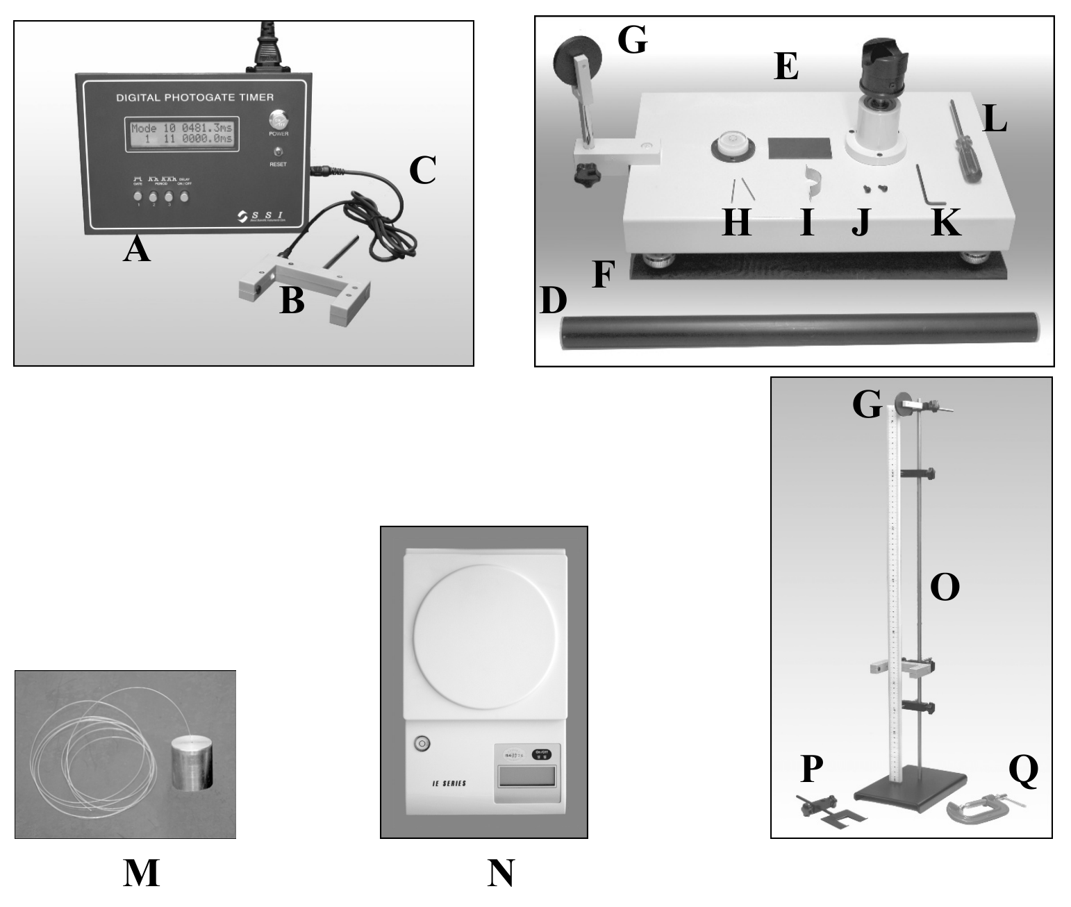
- List of available apparatus and materials
| Name | Quantity | Name | Quantity | ||
|---|---|---|---|---|---|
| A | Photogate timer | 1 | L | Philips screw driver | 1 |
| B | Photogate | 1 | M | Weight with a string | 1 |
| C | Connecting cable | 1 | N | Electronic balance | 1 |
| D | Mechanical “black box” (Black cylinder) | 1 | O | Stand with a ruler | 1 |
| E | Rotation stage | 1 | P | U-shaped support | 1 |
| F | Rubber pad | 1 | Q | C-clamp | 1 |
| G | Pulley | 2 | Ruler (0.50 m, 0.15 m) | 1 each | |
| H | Pin | 2 | Vernier calipers | 1 | |
| I | U-shaped plate | 1 | Scissors | 1 | |
| J | Screw | 2 | Thread | 1 | |
| K | Allen (hexagonal, L-shaped) wrench | 1 | Spares (string, thread, pin, screw, Allen wrench) |
2. Instruction for the Photogate Timer
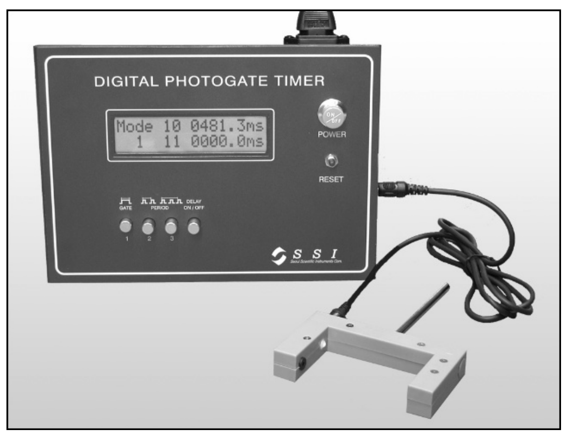
The Photogate consists of an infrared LED and a photodetector. By connecting the Photogate to the Photogate Timer, you can measure the time duration related to the blocking of the infrared light reaching the sensor.
- Be sure that the Photogate is connected to the Photogate Timer. Turn on the power by pushing the button labelled “POWER”.
- To measure the time duration of a single blocking event, push the button labelled “GATE”. Use this “GATE” mode for speed measurements.
- To measure the time interval between two or three successive blocking events, push the corresponding “PERIOD”. Use this “PERIOD” mode for oscillation measurements.
- If “DELAY” button is pushed in, the Photogate Timer displays the result of each measurement for 5 seconds and then resets itself.
- If “DELAY” button is pushed out, the Photogate Timer displays the result of the previous measurement until the next measurement is completed.
- After any change of button position, press the “RESET” button once to activate the mode change.
Caution: Do not look directly into the Photogate. The invisible infrared light may be harmful to your eyes.
3. Instruction for the Electronic Balance
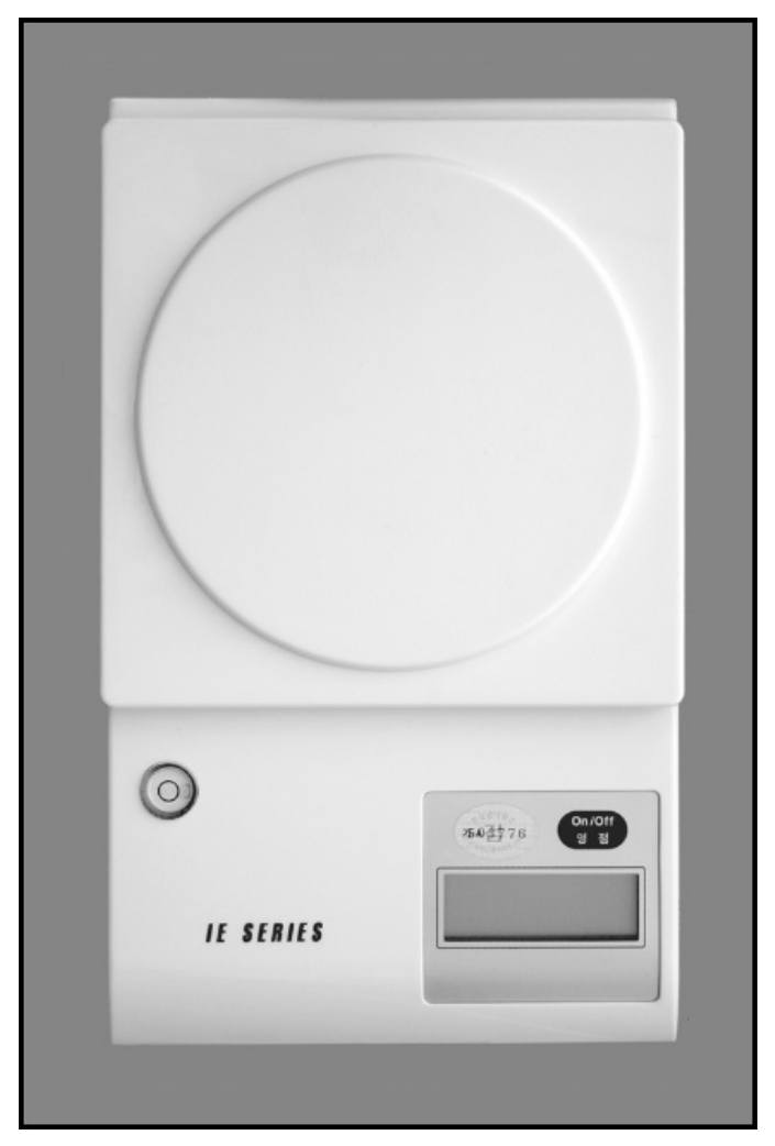
- Adjust the bottom legs to set the balance stable. (Although there is a level indicator, setting the balance in a completely horizontal position is not necessary.)
- Without putting anything on the balance, turn it on by pressing the “On/Off” button.
- Place an object on the round weighing pan. Its mass will be displayed in grams.
- If there is nothing on the weighing pan, the balance will be turned off automatically in about 25 seconds.
4. Instruction for the Rotation Stage
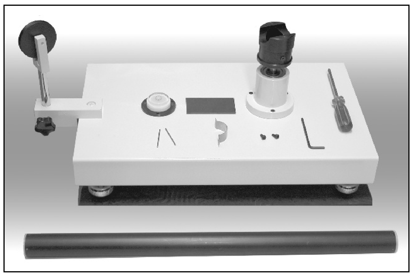
- Adjust the bottom legs to set the rotation stage stable on a rubber pad in a near horizontal position.
- With a U-shaped plate and two screws, mount the Mechanical “Black Box” (black cylinder) on the top of the rotating stub. Use Allen (hexagonal, L-shaped) wrench to tighten the screws.
- The string attached to the weight is to be fixed to the screw on the side of the rotating stub. Use the Philips screw driver.
Caution: Do not look too closely at the Mechanical “Black Box” while it is rotating. Your eyes may get hurt.
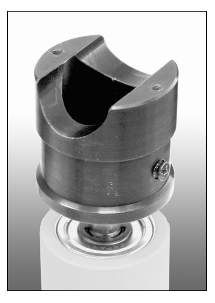
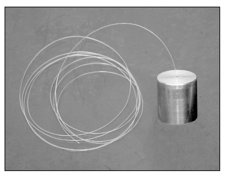
General Information on the Mechanical “Black Box”
[Question] Find the mass of the ball and the spring constants of two springs in the Mechanical “Black Box”.
The Mechanical “Black Box” (MBB) consists of a solid ball attached to two springs in a black cylindrical tube as shown in Fig. 1. The two springs are fashioned from the same tightly wound spring with different number of turns. The masses and the lengths of the springs when they are not extended can be ignored. The tube is homogeneous and sealed with two identical end caps. The part of the end caps plugged into the tube is 5 mm long. The radius of the ball is 11 mm and the inner diameter of the tube is 23 mm. The gravitational acceleration is given as . There is a finite friction between the ball and the inner walls of the tube.
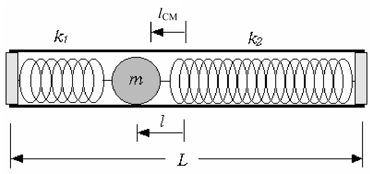
Fig. 1 Mechanical “Black Box” (not to scale)
The purpose of this experiment is to find out the mass of the ball and the spring constants and of the springs without opening the MBB. The difficult aspect of this problem is that any single experiment cannot provide the mass or the position of the ball because the two quantities are interconnected. Here, is the distance between the centers of the tube and the ball when the MBB lies horizontally in equilibrium when the friction is zero.
The symbols listed below should be used to represent the physical quantities of interest. If you need to use other physical quantities, use symbols different from those already assigned below to avoid confusion.
Assigned Physical Symbols
Mass of the ball:
Radius of the ball: (= 11 mm)
Mass of the MBB excluding the ball:
Length of the black tube:
Length of each end cap extending into the tube: (= 5.0 mm)
Distance from the center-of-mass of the MBB to the center of the tube:
Distance between the center of the ball and the center of the tube: (or at equilibrium when the MBB is horizontal)
Gravitational acceleration: (= )
Mass of the weight attached to a string:
Speed of the weight:
Downward displacement of the weight:
Radius of the rotating stub where the string is to be wound:
Moments of inertia: , , , , and so on
Angular velocity and angular frequencies: , , , and so on
Periods of oscillation: ,
Effective total spring constant:
Spring constants of the two springs: ,
Number of turns of the springs: ,
Caution: Do not try to open the MBB. If you open it, you will be disqualified and your mark in the Experimental Competition will be zero.
Caution: Do not shake violently nor drop the MBB. The ball may be detached from the springs. If your MBB seems faulty, report to the proctors immediately. It will be replaced only once without affecting your mark. Any further replacement will cut down your mark by 0.5 points each time.
PART-A Product of the mass and the position of the ball () (4 т.)
is the position of the center of the ball relative to that of the tube when the MBB lies horizontally in equilibrium as in Fig. 1. Find the value of the product of the mass and the position of the ball experimentally. You will need this to determine the value of in PART-B.
1. Suggest and justify, by using equations, a method allowing to obtain . [2 т.]
2. Experimentally determine the value of . [2 т.]
PART-B The mass of the ball (10 т.)
Figure 2 shows the MBB fixed horizontally on the rotating stub and a weight attached to one end of a string whose other end is wound on the rotating stub. When the weight falls, the string unwinds, and the MBB rotates. By combining the equation pertinent to this experiment with the one obtained in PART-A, you can find an equation for .
Between the ball and the inner walls of the cylindrical tube acts a frictional force. The physical mechanisms of the friction and the slipping of the ball under the rotational motion are complicated. To simplify the analysis, you may ignore the energy dissipation due to kinetic friction.
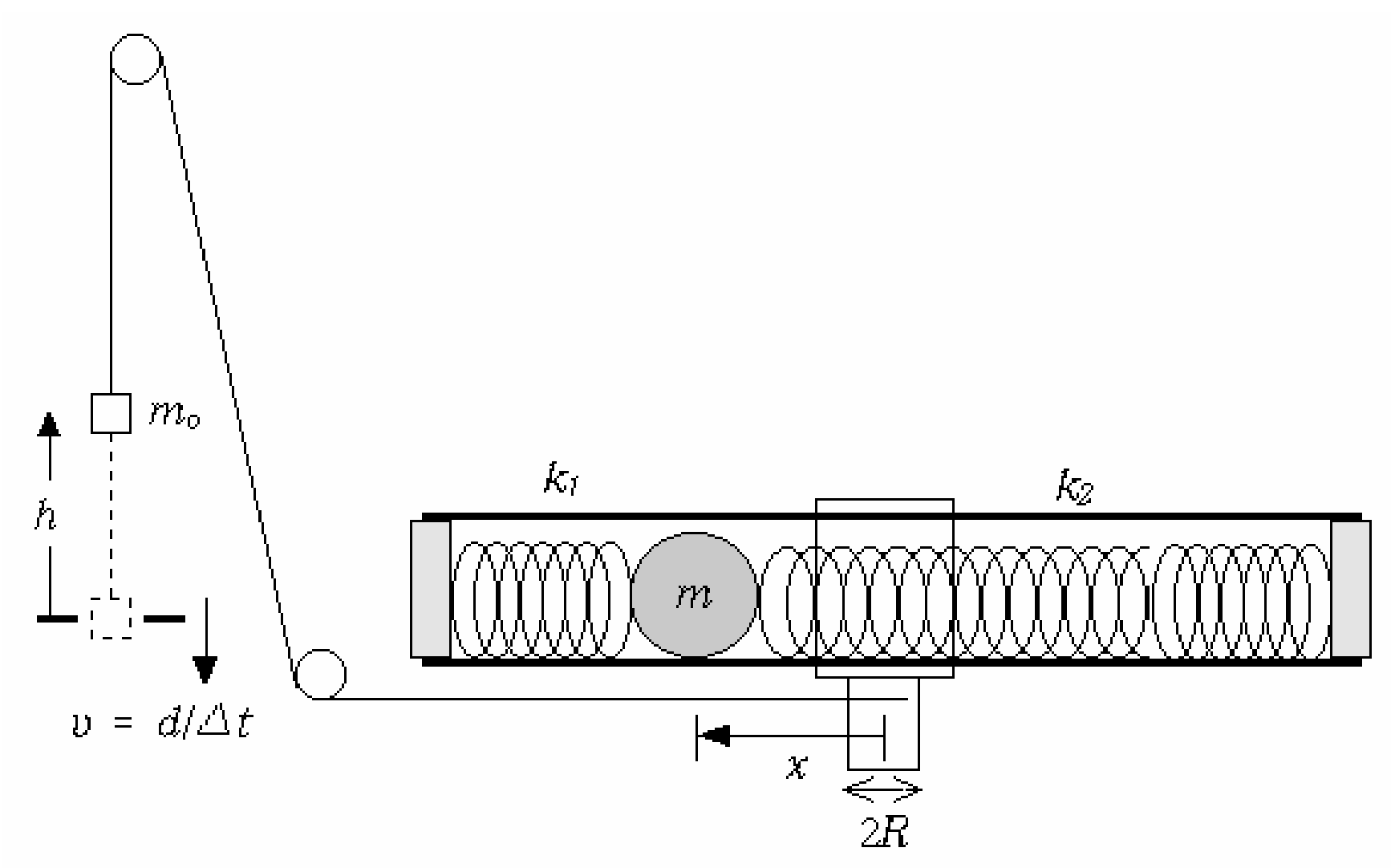
Fig. 2 Rotation of the Mechanical “Black Box” (not to scale)
The angular velocity of the MBB can be obtained from the speed of the weight passing through the Photogate. is the position of the ball relative to the rotation axis, and is the length of the weight.
1. Measure the speed of the weight for various values of downward displacement of the weight. It is recommended to scan the whole range from m to m by measuring just once at each with an interval of ~ m. Plot the data on graph paper in a form that is suitable to find the value of . After you get a general idea of the relation between and , you may repeat the measurement or add some data points, if necessary. When the MBB rotates slowly, the ball does not slip from its static equilibrium position because of the friction between the ball and the tube. When the MBB rotates sufficiently fast, the ball hits and actually stays at the end cap of the tube because the springs are weak. Identify the slow rotation region and the fast rotation region on the graph. [4 т.]
2. Show your measurements are consistent with the fact that is proportional to ( ) in the slow rotation region. Show from your measurements that in the fast rotation region. [1 т.]
3. The moment of inertia of a ball of radius and mass about the axis passing through its center is . If the ball is displaced a distance perpendicular to the axis, the moment of inertia increases by . Use the symbol to represent the total moment of inertia of all the rotating bodies excluding the ball. Relate the coefficient to the parameters of the MBB such as , , etc. [1 т.]
4. Relate the coefficients and to the parameters of the MBB such as , , etc. [1 т.]
5. Determine the value of from your measurements and the results obtained in PART-A. [3 т.]
PART-C The spring constants and (6 т.)
In this part, you need to perform small oscillation experiments using the MBB as a rigid pendulum. There are two small holes at each end of the MBB. Two thin pins inserted into the holes can be used as the pivot of small oscillation. The U-shaped support is to be clamped to the stand and used to support the pivot. Note that the angular frequency of small oscillation is given as = [torque/(moment of inertia angle)]. Here, the torque and the moment of inertia are with respect to the pivot. Similarly to PART-B, consider two experimental conditions, shown in Fig. 3, to avoid the unknown moment of inertia of the MBB excluding the ball.
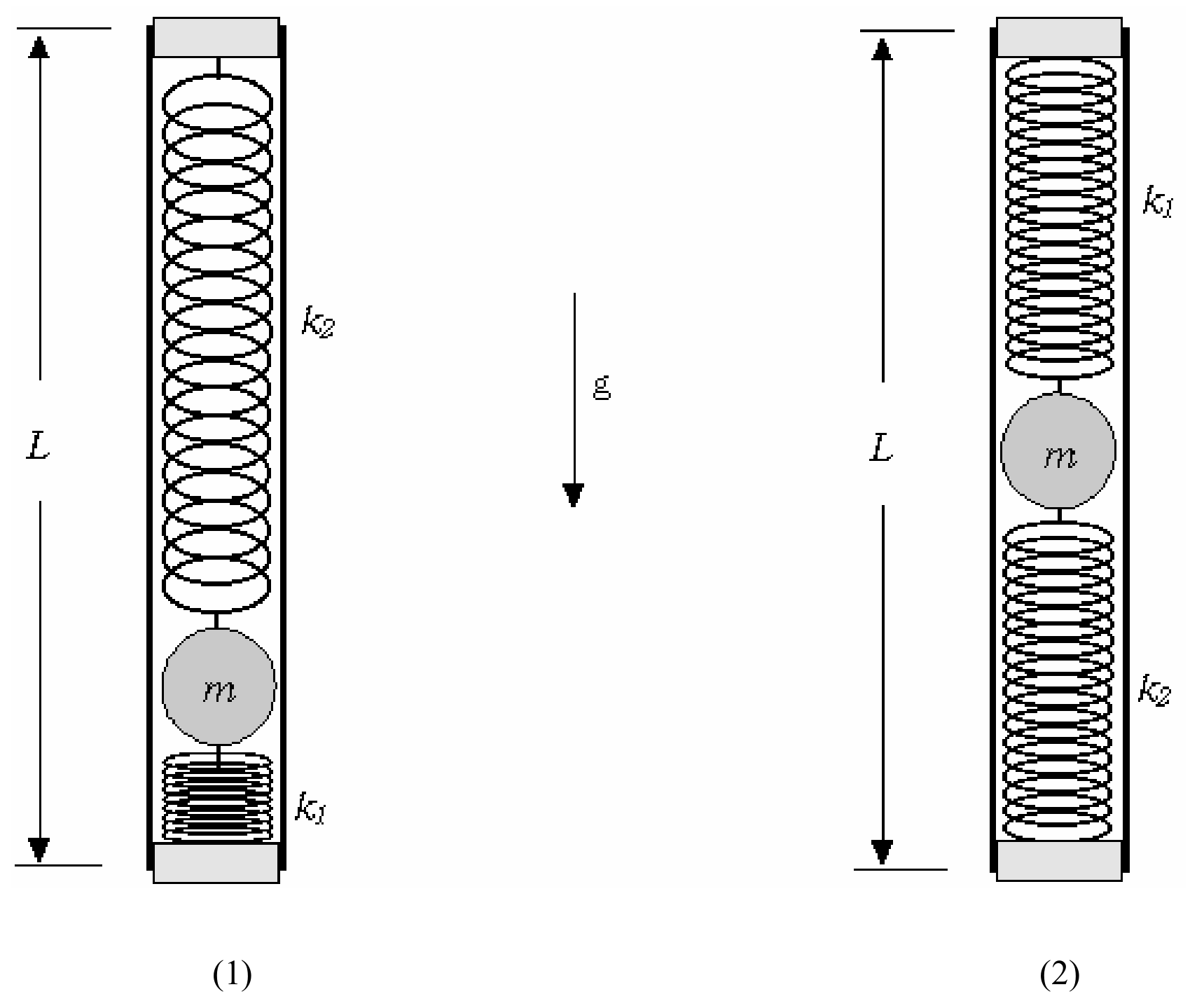
Fig. 3 Oscillation of the Mechanical “Black Box” (not to scale)
The periods of small oscillation, and , for two configurations shown above can be measured using the Photogate. Two pins and a U-shaped support are supplied for this experiment.
1. Measure the periods and of small oscillation shown in Figs 3(1) and (2) and write down their values, respectively. [1 т.]
2. Explain (by using equations) why the angular frequencies and of small oscillation of the configurations are different. Use the symbol to represent the moment of inertia of the MBB excluding the ball for the axis perpendicular to the MBB at the end. Use the symbol as the displacement of the ball from the horizontal equilibrium position. [1 т.]
3. Evaluate by eliminating from the previous results. [1 т.]
4. By combining the results of PART-C 1~3 and PART-B, find and write down the value of the effective total spring constant of the two-spring system. [2 т.]
5. Obtain the respective values of and . Write down their values. [1 т.]
Отговори
PART-A Product of the mass and the position of the ball (), 2. 0.00296 kg·m
Official value .
PART-B The mass of the ball, 5. 0.062 kg
Official value .
PART-C The spring constants and , 1. T₁ = 1.1090 s, T₂ = 1.0193 s
Official averages s and s.
PART-C The spring constants and , 3. 0.072 m
Official value m.
PART-C The spring constants and , 4. 9 N/m
Official value N/m.
PART-C The spring constants and , 5. k₁ = 5.7 N/m, k₂ = 3 N/m
Official values N/m and N/m.
Решение
PART-A Product of the mass and the position of the ball ()
1. Suggest and justify, by using equations, a method allowing to obtain . (2.0 points)
(Explanation) The lever rule is applied to the Mechanical “Black Box”, shown in Fig. A-1, once the position of the center of mass of the whole system is found.
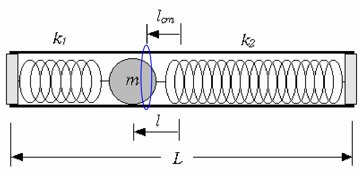
Fig. A-1 Experimental setup
2. Experimentally determine the value of . (2.0 points)
(Explanation) The measured quantities are
and
Therefore
PART-B The mass of the ball
1. Measure for various values of . Plot the data on a graph paper in a form that is suitable to find the value of . Identify the slow rotation region and the fast rotation region on the graph. (4.0 points)
2. Show from your measurements that in the slow rotation region, and in the fast rotation region. (1.0 points)
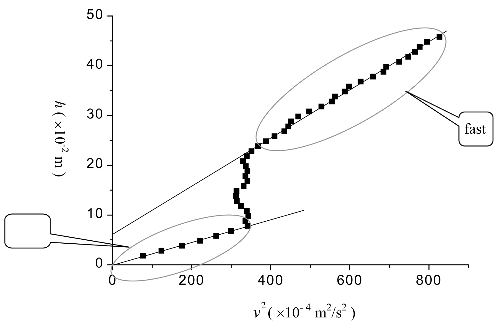
(Explanation) The measured data are
| ( m) a) | (ms) | ( m) b) | ( m/s) c) | ( m²/s²) | |
|---|---|---|---|---|---|
| 1 | 25.5±0.1 | 269.4±0.05 | 1.8±0.1 | 8.75±0.02 | 76.6±0.2 |
| 2 | 26.5±0.1 | 235.7±0.05 | 2.8±0.1 | 11.12±0.02 | 123.7±0.3 |
| 3 | 27.5±0.1 | 197.9±0.05 | 3.8±0.1 | 13.24±0.03 | 175.3±0.6 |
| 4 | 28.5±0.1 | 176.0±0.05 | 4.8±0.1 | 14.89±0.03 | 221.7±0.6 |
| 5 | 29.5±0.1 | 161.8±0.05 | 5.8±0.1 | 16.19±0.03 | 262.1±0.7 |
| 6 | 30.5±0.1 | 151.4±0.05 | 6.8±0.1 | 17.31±0.03 | 299.6±0.7 |
| 7 | 31.5±0.1 | 141.8±0.05 | 7.8±0.1 | 18.48±0.04 | 342±1 |
| 8 | 32.5±0.1 | 142.9±0.05 | 8.8±0.1 | 18.33±0.04 | 336±1 |
| 9 | 33.5±0.1 | 141.4±0.05 | 9.8±0.1 | 18.53±0.04 | 343±1 |
| 10 | 34.5±0.1 | 142.2±0.05 | 10.8±0.1 | 18.42±0.04 | 339±1 |
| 11 | 35.5±0.1 | 145.4±0.05 | 11.8±0.1 | 18.02±0.04 | 325±1 |
| 12 | 36.5±0.1 | 147.8±0.05 | 12.8±0.1 | 17.73±0.04 | 314±1 |
| 13 | 37.5±0.1 | 148.3±0.05 | 13.8±0.1 | 17.67±0.04 | 312±1 |
| 14 | 38.5±0.1 | 148.0±0.05 | 14.8±0.1 | 17.70±0.04 | 313±1 |
| 15 | 39.5±0.1 | 143.9±0.05 | 15.8±0.1 | 18.21±0.04 | 332±1 |
| 16 | 40.5±0.1 | 141.9±0.05 | 16.8±0.1 | 18.46±0.04 | 341±1 |
| 17 | 41.5±0.1 | 142.9±0.05 | 17.8±0.1 | 18.33±0.04 | 336±1 |
| 18 | 42.5±0.1 | 141.9±0.05 | 18.8±0.1 | 18.46±0.04 | 341±1 |
| 19 | 43.5±0.1 | 142.8±0.05 | 19.8±0.1 | 18.35±0.04 | 337±1 |
| 20 | 44.5±0.1 | 144.3±0.05 | 20.8±0.1 | 18.16±0.04 | 330±1 |
| 21 | 45.5±0.1 | 142.2±0.05 | 21.8±0.1 | 18.42±0.04 | 339±1 |
| 22 | 46.5±0.1 | 139.8±0.05 | 22.8±0.1 | 18.74±0.04 | 351±1 |
| 23 | 47.5±0.1 | 136.7±0.05 | 23.8±0.1 | 19.17±0.04 | 368±1 |
| 24 | 48.5±0.1 | 133.0±0.05 | 24.8±0.1 | 19.70±0.04 | 388±1 |
| 25 | 49.5±0.1 | 129.5±0.05 | 25.8±0.1 | 20.23±0.04 | 409±1 |
| 26 | 50.5±0.1 | 125.7±0.05 | 26.8±0.1 | 20.84±0.04 | 434±1 |
| 27 | 51.5±0.1 | 124.3±0.05 | 27.8±0.1 | 21.08±0.04 | 444±1 |
| 28 | 52.5±0.1 | 123.4±0.05 | 28.8±0.1 | 21.23±0.04 | 451±1 |
| 29 | 53.5±0.1 | 120.9±0.05 | 29.8±0.1 | 21.67±0.04 | 470±1 |
| 30 | 54.5±0.1 | 117.5±0.05 | 30.8±0.1 | 22.30±0.04 | 497±1 |
| 31 | 55.5±0.1 | 114.0±0.05 | 31.8±0.1 | 22.98±0.04 | 528±1 |
| 32 | 56.5±0.1 | 111.2±0.05 | 32.8±0.1 | 23.56±0.05 | 555±2 |
| 33 | 57.5±0.1 | 110.5±0.05 | 33.8±0.1 | 23.71±0.05 | 562±2 |
| 34 | 58.5±0.1 | 108.1±0.05 | 34.8±0.1 | 24.24±0.05 | 588±2 |
| 35 | 59.5±0.1 | 107.1±0.05 | 35.8±0.1 | 24.46±0.05 | 598±2 |
| 36 | 60.5±0.1 | 104.6±0.05 | 36.8±0.1 | 25.05±0.05 | 628±2 |
| 37 | 61.5±0.1 | 102.1±0.05 | 37.8±0.1 | 25.66±0.05 | 658±2 |
| 38 | 62.5±0.1 | 100.1±0.05 | 38.8±0.1 | 26.17±0.05 | 685±2 |
| 39 | 63.5±0.1 | 99.6±0.05 | 39.8±0.1 | 26.31±0.05 | 692±2 |
| 40 | 64.5±0.1 | 97.3±0.05 | 40.8±0.1 | 26.93±0.05 | 725±2 |
| 41 | 65.5±0.1 | 95.8±0.05 | 41.8±0.1 | 27.35±0.05 | 748±2 |
| 42 | 66.5±0.1 | 94.7±0.05 | 42.8±0.1 | 27.67±0.05 | 766±2 |
| 43 | 67.5±0.1 | 94.0±0.05 | 43.8±0.1 | 27.87±0.06 | 777±2 |
| 44 | 68.5±0.1 | 92.9±0.05 | 44.8±0.1 | 28.20±0.06 | 795±2 |
| 45 | 69.5±0.1 | 91.1±0.05 | 45.8±0.1 | 28.76±0.06 | 827±2 |
where
a) is the reading of the top position of the weight before it starts to fall,
b) is the distance of fall of the weight which is obtained by , (= m) is the top position of the weight at the start of blocking of the photogate, (= m) is the length of the weight, and
c) is obtained from .
3. Relate the coefficient to the parameters of the MBB. (1.0 points)
(Explanation) The ball is at static equilibrium (). When the speed of the weight is , the increase in kinetic energy of the whole system is given by
where (= ) is the angular velocity of the Mechanical “Black Box” and is the effective moment of inertia of the whole system except the ball. Since the decrease in gravitational potential energy of the weight is
the energy conservation () gives
4. Relate the coefficients and to the parameters of the MBB. (1.0 points)
(Explanation) The ball stays at the end cap of the tube (). When the speed of the weight is , the increase in kinetic energy of the whole system is given by
Since the increase in elastic potential energy of the springs is
the energy conservation () gives
where
and
5. Determine the value of from your measurements and the results obtained in PART-A. (3.0 points)
(Explanation) From the results obtained in PART-B 3 and 4 we get
The measured values are
Therefore,
and
The slopes of the two straight lines in the graph (Fig. B-1) of PART-B 1 are
respectively, and
Since we already obtained from PART-A, the equation
or
is resulted, where is expressed in the unit of g.
The roots of this equation are
The physically meaningful positive root is
PART-C The spring constants and
1. Measure the periods and of small oscillation shown in Figs. 3 (1) and (2) and write down their values, respectively. (1.0 points)
(Explanation)
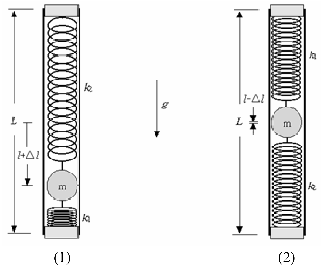
The measured periods are
| (s) | (s) | ||
|---|---|---|---|
| 1 | 1.1085±0.00005 | 1 | 1.0194±0.00005 |
| 2 | 1.1092±0.00005 | 2 | 1.0194±0.00005 |
| 3 | 1.1089±0.00005 | 3 | 1.0193±0.00005 |
| 4 | 1.1085±0.00005 | 4 | 1.0191±0.00005 |
| 5 | 1.1094±0.00005 | 5 | 1.0192±0.00005 |
| 6 | 1.1090±0.00005 | 6 | 1.0194±0.00005 |
| 7 | 1.1088±0.00005 | 7 | 1.0194±0.00005 |
| 8 | 1.1090±0.00005 | 8 | 1.0191±0.00005 |
| 9 | 1.1092±0.00005 | 9 | 1.0192±0.00005 |
| 10 | 1.1094±0.00005 | 10 | 1.0193±0.00005 |
By averaging the10 measurements for each configuration, respectively, we get
2. Explain, by using equations, why the angular frequencies and of small oscillation of the configurations are different. (1.0 points)
(Explanation) The moment of inertia of the Mechanical “Black Box” with respect to the pivot at the top of the tube is
depending on the orientation of the MBB as shown in Figs. C-1(1) and (2), respectively.
When the MBB is slightly tilted by an angle from vertical, the torque applied by the gravity is
or
depending on the orientation.
Therefore, the angular frequencies of oscillation become
and
3. Evaluate by eliminating from the previous results. (1.0 points)
(Explanation) By rewriting the two expressions for the angular frequencies and as
and
one can eliminate the unknown moment of inertia of the MBB without the ball.
By eliminating the one gets the equation for
From the measured or given values we get,
Therefore, the equation we obtained in PART-C 3 becomes
where is expressed in the unit of cm. By solving the equation we get
4. Write down the value of the effective total spring constant of the two-spring system. (2.0 points)
(Explanation) The effective total spring constant is
5. Obtain the respective values of and . Write down their values. (1.0 point)
(Explanation) When the MBB is in equilibrium on a horizontal plane the force balance condition for the ball is that
Since , we get
and
From the measured or given values
Therefore,
and
Оригинал в Архива: exp.pdf · официални решения: exp_sol.pdf · допълнителни данни: IPhO_2004_Experimental Question.pdf · допълнителни данни: IPhO_2004_Experimental Solution.pdf