IPhO 2005, Теория — Задача 2. ABSOLUTE MEASUREMENTS OF ELECTRICAL QUANTITIES
36th International Physics Olympiad. Salamanca (España) 2005 · 10 т.
Условие
The technological and scientific transformations underwent during the XIX century produced a compelling need of universally accepted standards for the electrical quantities. It was thought the new absolute units should only rely on the standards of length, mass and time established after the French Revolution. An intensive experimental work to settle the values of these units was developed from 1861 until 1912. We propose here three case studies.
Marks are indicated at the beginning of each subquestion, in parenthesis.
Determination of the ohm (Kelvin)
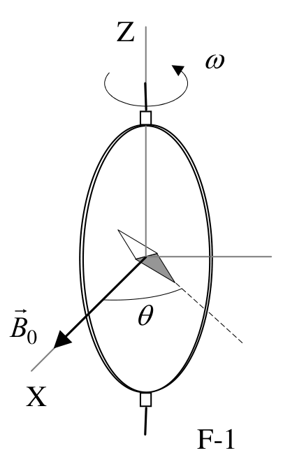
A closed circular coil of turns, radius and total resistance is rotated with uniform angular velocity about a vertical diameter in a horizontal magnetic field .
1. (0.5+1.0) Compute the electromotive force induced in the coil, and also the mean power required for maintaining the coil in motion. Neglect the coil self inductance. [1,5 т.]
A small magnetic needle is placed at the center of the coil, as shown in Figure F-1. It is free to turn slowly around the Z axis in a horizontal plane, but it cannot follow the rapid rotation of the coil.
2. (2.0) Once the stationary regime is reached, the needle will set at a direction making a small angle with . Compute the resistance of the coil in terms of this angle and the other parameters of the system. [2 т.]
Lord Kelvin used this method in the 1860s to set the absolute standard for the ohm. To avoid the rotating coil, Lorenz devised an alternative method used by Lord Rayleigh and Ms. Sidgwick, that we analyze in the next paragraphs.
Determination of the ohm (Rayleigh, Sidgwick).
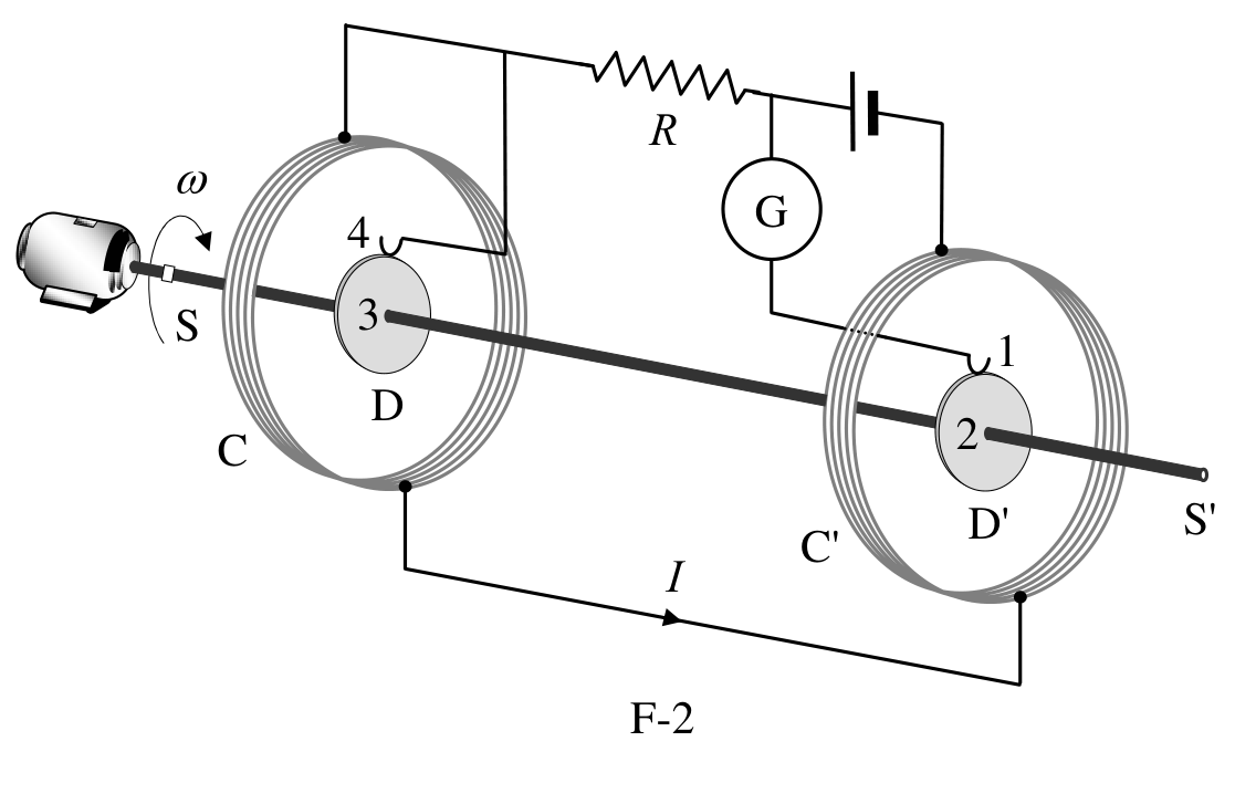
The experimental setup is shown in Figure F-2. It consists of two identical metal disks D and D' of radius mounted on the conducting shaft SS'. A motor rotates the set at an angular velocity , which can be adjusted for measuring . Two identical coils C and C' (of radius and with turns each) surround the disks. They are connected in such a form that the current flows through them in opposite directions. The whole apparatus serves to measure the resistance .
3. (2.0) Assume that the current flowing through the coils C and C' creates a uniform magnetic field around D and D', equal to the one at the centre of the coil. Compute the electromotive force induced between the rims 1 and 4, assuming that the distance between the coils is much larger than the radius of the coils and that . [2 т.]
The disks are connected to the circuit by brush contacts at their rims 1 and 4. The galvanometer G detects the flow of current through the circuit 1-2-3-4.
4. (0.5) The resistance is measured when G reads zero. Give in terms of the physical parameters of the system. [0,5 т.]
Determination of the ampere
Passing a current through two conductors and measuring the force between them provides an absolute determination of the current itself. The “Current Balance” designed by Lord Kelvin in 1882 exploits this method. It consists of six identical single turn coils C… C of radius , connected in series. As shown in Figure F-3, the fixed coils C, C, C, and C are on two horizontal planes separated by a small distance . The coils C and C are carried on balance arms of length , and they are, in equilibrium, equidistant from both planes.
The current flows through the various coils in such a direction that the magnetic force on C is upwards while that on C is downwards. A mass at a distance from the fulcrum O is required to restore the balance to the equilibrium position described above when the current flows through the circuit.
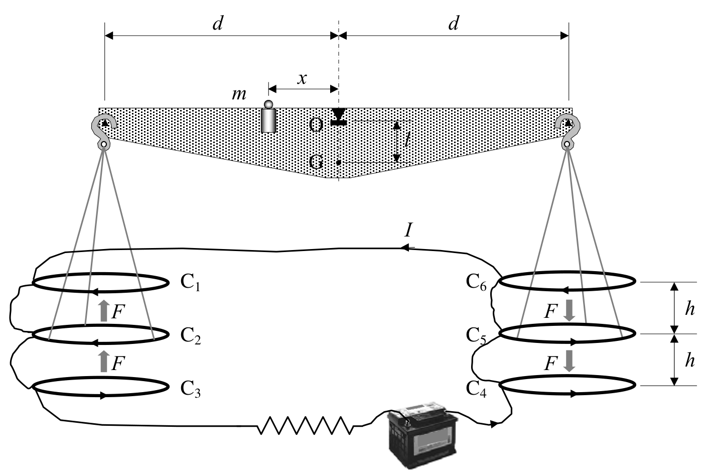
5. (1.0) Compute the force on C due to the magnetic interaction with C. For simplicity assume that the force per unit length is the one corresponding to two long, straight wires carrying parallel currents. [1 т.]
6. (1.0) The current is measured when the balance is in equilibrium. Give the value of in terms of the physical parameters of the system. The dimensions of the apparatus are such that we can neglect the mutual effects of the coils on the left and on the right. [1 т.]
Let be the mass of the balance (except for and the hanging parts), G its centre of mass and the distance .
7. (2.0) The balance equilibrium is stable against deviations producing small changes in the height of C and in C. Compute the maximum value so that the balance still returns towards the equilibrium position when it is released. [2 т.]
The mean value of a quantity in a periodic system of period is
You may need one or more of these integrals:
Consider that the coils centres remain approximately aligned.
Use the approximations or for , and for small .
| COUNTRY CODE | STUDENT CODE | PAGE NUMBER | TOTAL No OF PAGES |
|---|---|---|---|
Th 2 ANSWER SHEET
| Question | Basic formulas used | Analytical results | Marking guideline |
|---|---|---|---|
| 1 | 1.5 | ||
| 2 | 2.0 | ||
| 3 | 2.0 | ||
| 4 | 0,5 | ||
| 5 | 1.0 | ||
| 6 | 1.0 | ||
| 7 | 2.0 |
Отговори
- 1.
- 2.
- 3.
- 4.
- 5.
- 6.
- 7.
Решение
1. After some time , the normal to the coil plane makes an angle with the magnetic field . Then, the magnetic flux through the coil is
where the vector surface is given by
Therefore
The induced electromotive force is
The instantaneous power is , therefore
where we used
2. The total field at the center the coil at the instant is
where is the magnetic field due to the induced current
with and
Therefore
The mean values of its components are
And the mean value of the total magnetic field is
The needle orients along the mean field, therefore
Finally, the resistance of the coil measured by this procedure, in terms of , is
3. The force on a unit positive charge in a disk is radial and its modulus is
where is the magnetic field at the center of the coil
Then, the electromotive force (e.m.f.) induced on each disk by the magnetic field is
Finally, the induced e.m.f. between 1 and 4 is
4. When the reading of G vanishes, and Kirchoff laws give an immediate answer. Then we have
5. The force per unit length between two indefinite parallel straight wires separated by a distance is.
for and length , the force induced on C by the neighbor coils C is
6. In equilibrium
Then
so that
7. The balance comes back towards the equilibrium position for a little angular deviation if the gravity torques with respect to the fulcrum O are greater than the magnetic torques.
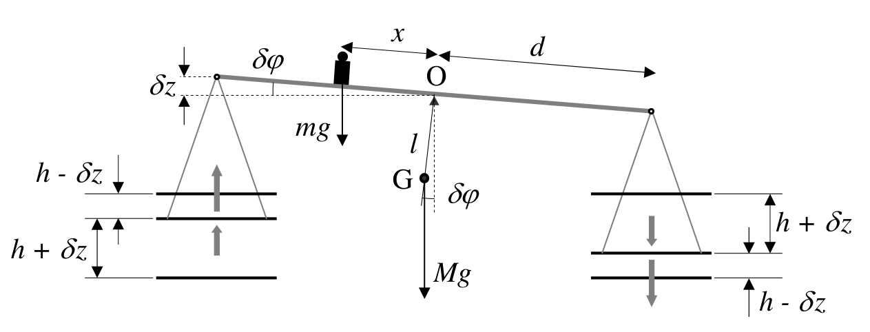
Therefore, using the suggested approximation
Taking into account the equilibrium condition (1), one obtains
Finally, for
Th 2 ANSWER SHEET
| Question | Basic formulas and ideas used | Analytical results | Marking guideline |
|---|---|---|---|
| 1 | ; ; | ; | 0.5; 1.0 |
| 2 | ; ; | 2.0 | |
| 3 | ; ; ; | 2.0 | |
| 4 | 0,5 | ||
| 5 | 1.0 | ||
| 6 | 1.0 | ||
| 7 | 2.0 |