IPhO 2010, Експеримент — Задача 2. Experimental problem 2: Forces between magnets, concepts of stability and symmetry
41st International Physics Olympiad – Experimental Competition, July 21st, 2010. Experimental problem 2 · 21 юли 2010 г. · 10 т.
Условие
There are two experimental problems. The setup on your table is used for both problems. You have 5 hours to complete the entire task (1&2).
Introduction
Electric current circulating in a loop of area creates a magnetic moment of magnitude [see Fig. 1(a)]. A permanent magnet can be thought of as a collection of small magnetic moments of iron (Fe), each of which is analogous to the magnetic moment of a current loop. This (Ampère’s) model of a magnet is illustrated in Fig. 1(b). The total magnetic moment is a sum of all small magnetic moments, and it points from the south to the northern pole.

Forces between magnets
To calculate the force between two magnets is a nontrivial theoretical task. It is known that like poles of two magnets repel, and unlike poles attract. The force between two current loops depends on the strengths of the currents in them, their shape, and their mutual distance. If we reverse the current in one of the loops, the force between them will be of the same magnitude, but of the opposite direction.
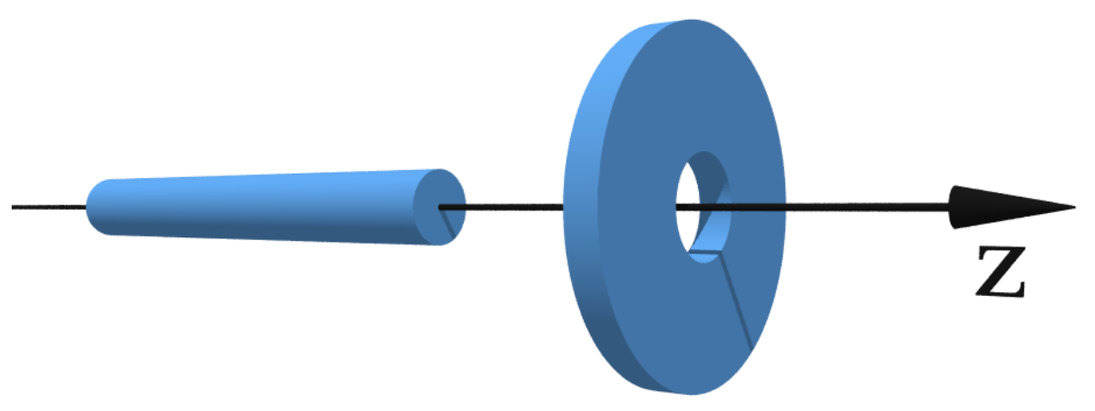
In this problem you experimentally investigate the forces between two magnets, the ring-magnet and the rod-magnet. We are interested in the geometry where the axes of symmetry of the two magnets coincide (see Fig. 2). The rod-magnet can move along the - axis from the left, through the ring-magnet, and then towards the right (see Fig. 2). Among other tasks, you will be asked to measure the force between the magnets as a function of . The origin corresponds to the case when the centers of the magnets coincide.
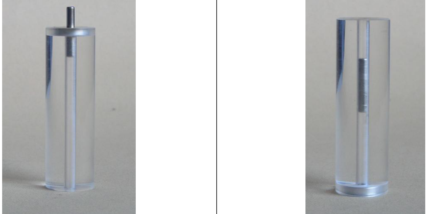
To ensure motion of the rod-magnet along the axis of symmetry ( - axis), the ring-magnet is firmly embedded in a transparent cylinder, which has a narrow hole drilled along the - axis. The rod-magnet is thus constrained to move along the - axis through the hole (see Fig. 3). The magnetization of the magnets is along the - axis. The hole ensures radial stability of the magnets.
Experimental setup (2 problem)
The following items (to be used for the 2 problem) are on your desk:
- Press (together with a stone block); see separate instructions if needed
- Scale (measures mass up to 5000 g, it has TARA function, see separate instructions if needed)
- A transparent hollow cylinder with a ring-magnet embedded in its side.
- One rod-magnet.
- One narrow wooden stick (can be used to push the rod magnet out of the cylinder).
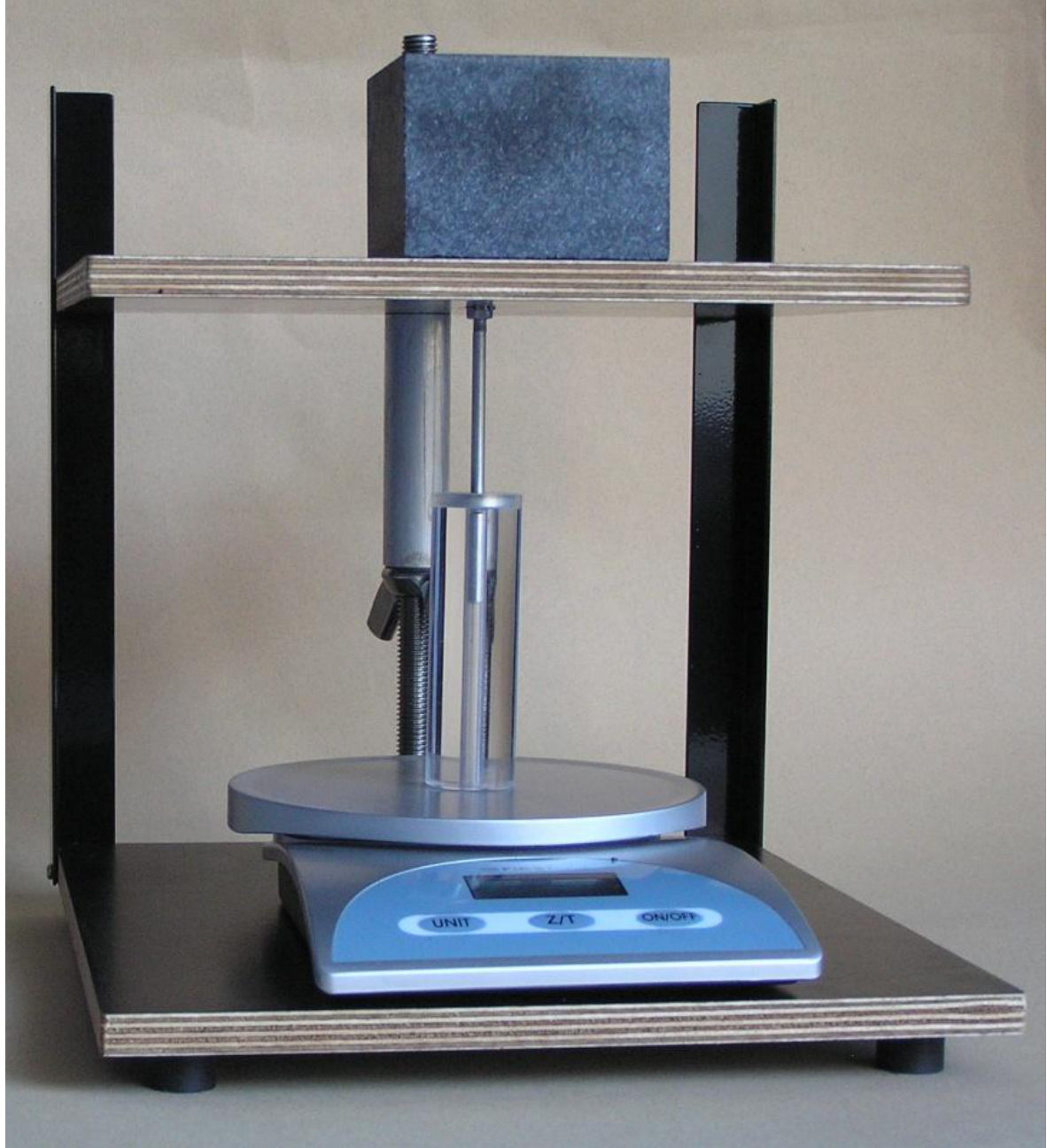
The setup is to be used as in Fig. 4 to measure the forces between the magnets. The upper plate of the press needs to be turned up-side-down in comparison to the first experimental problem. The narrow Aluminum rod is used to press the rod-magnet through the hollow cylinder. The scale measures the force (mass). The upper plate of the press can be moved downwards and upwards by using a wing nut. Important: The wing nut moves 2mm when rotated 360 degrees.
Tasks
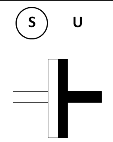
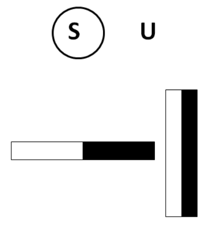
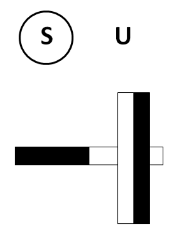
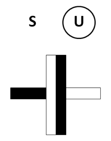
1. Determine qualitatively all equilibrium positions between the two magnets, assuming that the - axis is positioned horizontally as in Fig. 2 , and draw them in the answer sheet. Label the equilibrium positions as stable (S)/unstable (U), and denote the like poles by shading, as indicated for one stable position in the answer sheet. You can do this Task by using your hands and a wooden stick. (2.5 points)
2. By using the experimental setup measure the force between the two magnets as a function of the - coordinate. Let the positive direction of the - axis point into the transparent cylinder (the force is positive if it points in the positive direction). For the configuration when the magnetic moments are parallel, denote the magnetic force by , and when they are anti-parallel, denote the magnetic force by . Important: Neglect the mass of the rod-magnet (i.e., neglect gravity), and utilize the symmetries of the forces between magnets to measure different parts of the curves. If you find any symmetry in the forces, write them in the answer sheets. Write the measurements on the answer sheets; beside every table schematically draw the configuration of magnets corresponding to each table (an example is given). (3.0 points)
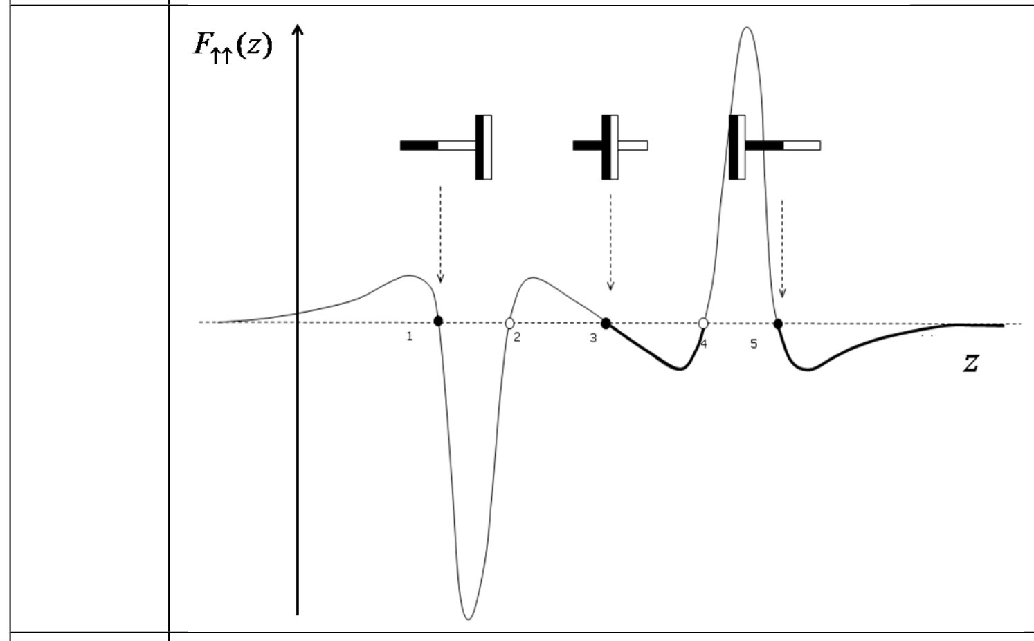
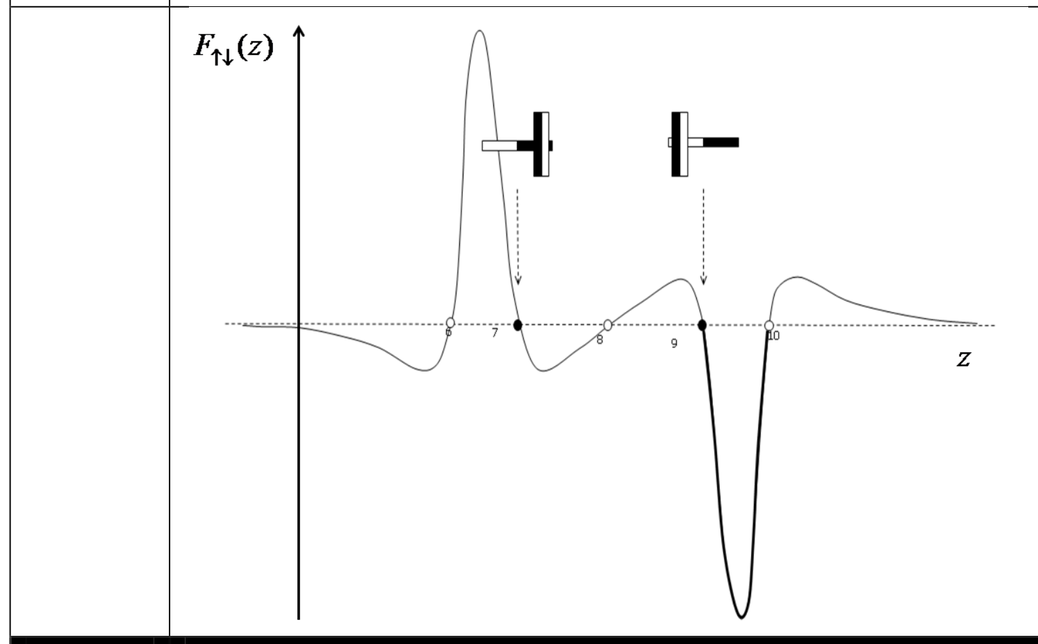
3. By using the measurements from Task 2, use the millimeter paper to plot in detail the functional dependence for . Plot schematically the shapes of the curves and (along the positive and the negative - axis). On each schematic graph denote the positions of the stable equilibrium points, and sketch the corresponding configuration of magnets (as in Task 1). (4.0 points)
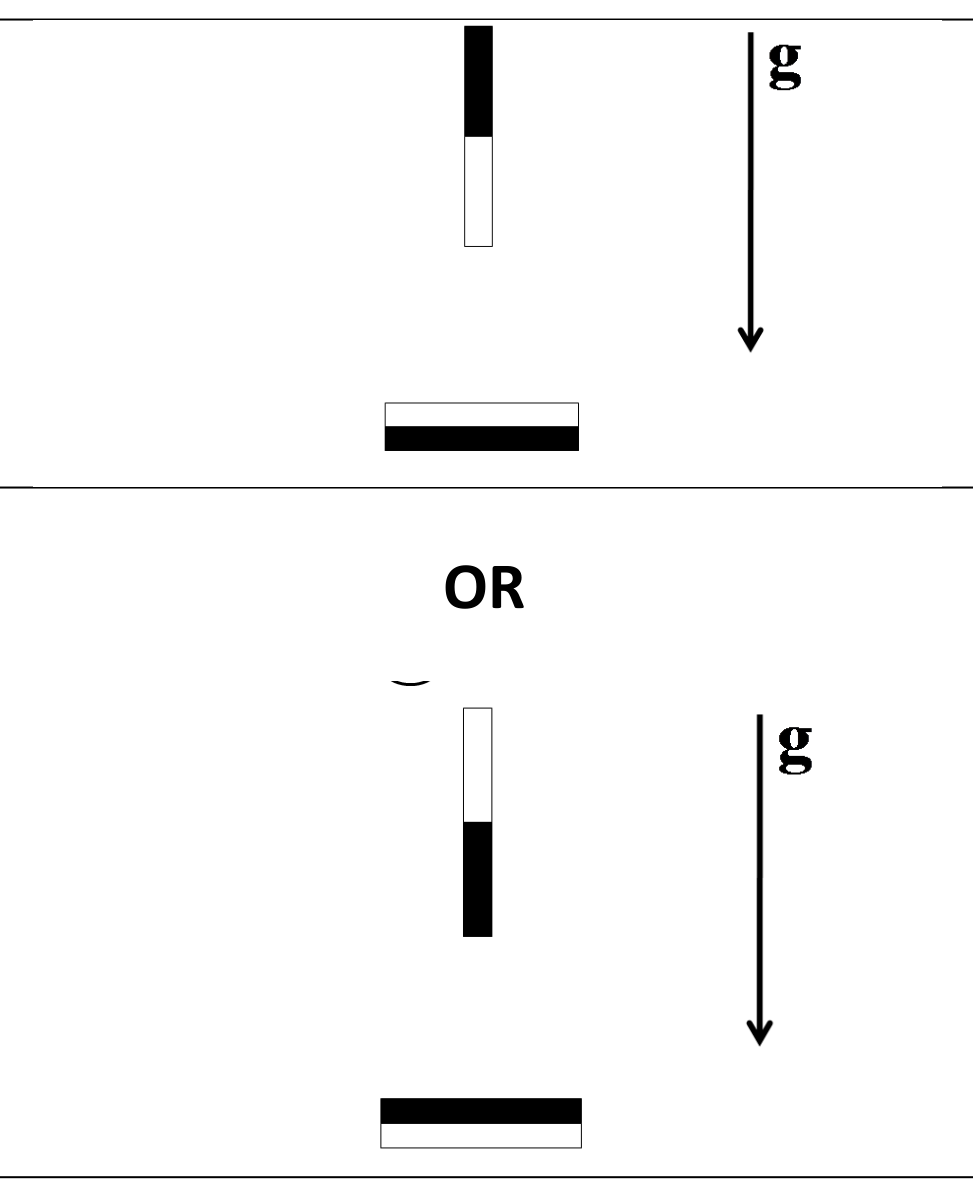
4. If we do not neglect the mass of the rod magnet, are there any qualitatively new stable equilibrium positions created when the - axis is positioned vertically? If so, plot them on the answer sheet as in Task 1. (0.5 points)
Решение
Task 1 — Points
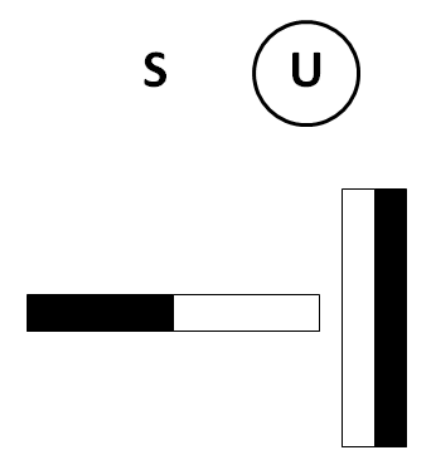
Six equilibrium configurations are drawn (figures below); in each, the correct label, S or U, is circled.
- S (circled) — 0.25
- S (circled) — 0.45
- S (circled) — 0.45
- U (circled) — 0.45
- U (circled) — 0.45
- U (circled) — 0.45
Task 2 — Points
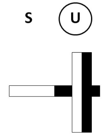
Symmetries that should be utilized in the measurements: 0,6
From the two above one gets also
By using the setup as it is, the whole curve can be measured by starting the measurements from three stable equilibrium points; the equilibrium point (z0) can be measured also by using the setup. 0,8
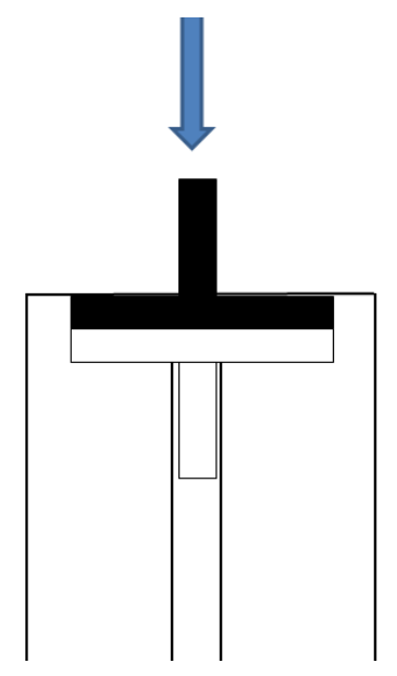
Configuration: (figure)
Measurements:
| z0=0mm | m [g] | Δz [mm] |
|---|---|---|
| 0 | 0 | |
| 31 | 1 | |
| 55 | 2 | |
| 75 | 3 | |
| 97 | 4 | |
| 119 | 5 | |
| 140 | 6 | |
| 158 | 7 | |
| 171 | 8 | |
| 170 | 9 | |
| 118 | 10 | |
| 85 | 10,25 | |
| 50 | 10,5 | |
| 10 | 10,75 |
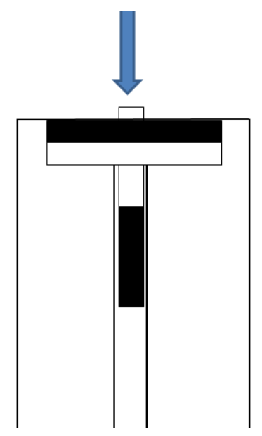
0,8
Configuration: (figure)
Measurements:
| z0=10.8mm | m [g] | Δz [mm] |
|---|---|---|
| 0 | 0 | |
| 233 | 1 | |
| 538 | 2 | |
| 927 | 3 | |
| 996 | 3,5 | |
| 1124 | 4 | |
| 1154 | 4,5 | |
| 1213 | 5 | |
| 1212 | 5,5 | |
| 1120 | 6 | |
| 873 | 6,5 | |
| 284 | 7 | |
| 36 | 7,5 |
0,8
Configuration: (figure)
Measurements:
| z0=18.6mm | m [g] | Δz [mm] |
|---|---|---|
| 0 | 0 | |
| 116 | 1 | |
| 170 | 2 | |
| 186 | 3 | |
| 184 | 4 | |
| 169 | 5 | |
| 150 | 6 | |
| 116 | 8 | |
| 89 | 10 | |
| 67 | 12 | |
| 53 | 14 | |
| 36 | 16 | |
| 27 | 18 | |
| 23 | 20 | |
| 14 | 22 | |
| 9 | 24 | |
| 5 | 26 | |
| 3 | 28 |
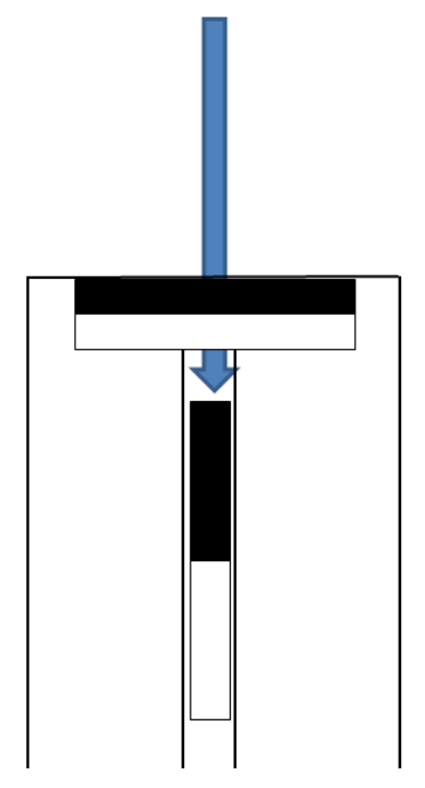
Task 3 — Points
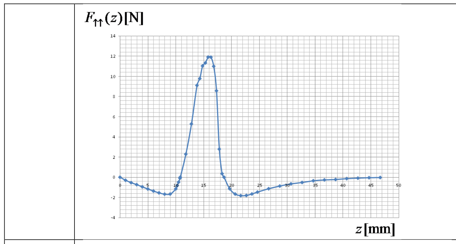
Due to symmetry, it is sufficient to plot e.g., the following graph in detail: 2
(detailed graph of [N] versus [mm])
Schematic graph of with the stable equilibrium configurations: 1
Schematic graph of with the stable equilibrium configurations: 1
Task 4 — Points
Two configurations are drawn (figure): 0,5
Total: 10.0
Оригинал в Архива: exp2.pdf · официални решения: exp2_sol.pdf