IPhO 2013, Експеримент — Задача 2.1. The dependence of the solar cell current on the distance to the light source
Solar cells — E2 · 7 юли 2013 г.
Warnings and notices
WARNING: Do not use the multimeter as an ohmmeter on the solar cells since the measuring current can damage them. When changing the measuring range on the multimeters, please turn the dial with caution. It can be unstable and may break. Check whether there is a number under the decimal point when measuring – if the dial is not fully in place, the multimeter will not measure, even if there are digits in the display.
Notice: Do not change the voltage on the power supply. It must be 12 V throughout the experiment. (The power supply for the light source should be connected to the outlet (230 V ~) at your table.)
Notice: Uncertainty considerations are only expected when explicitly mentioned.
Notice: All measured and calculated values must be given in SI units.
Notice: For all measurements of currents and voltages in this experiment, the LED-light source is supposed to be on.
Условие
2.0 Introduction
Equipment used for this experiment is displayed in Fig. 2.1.
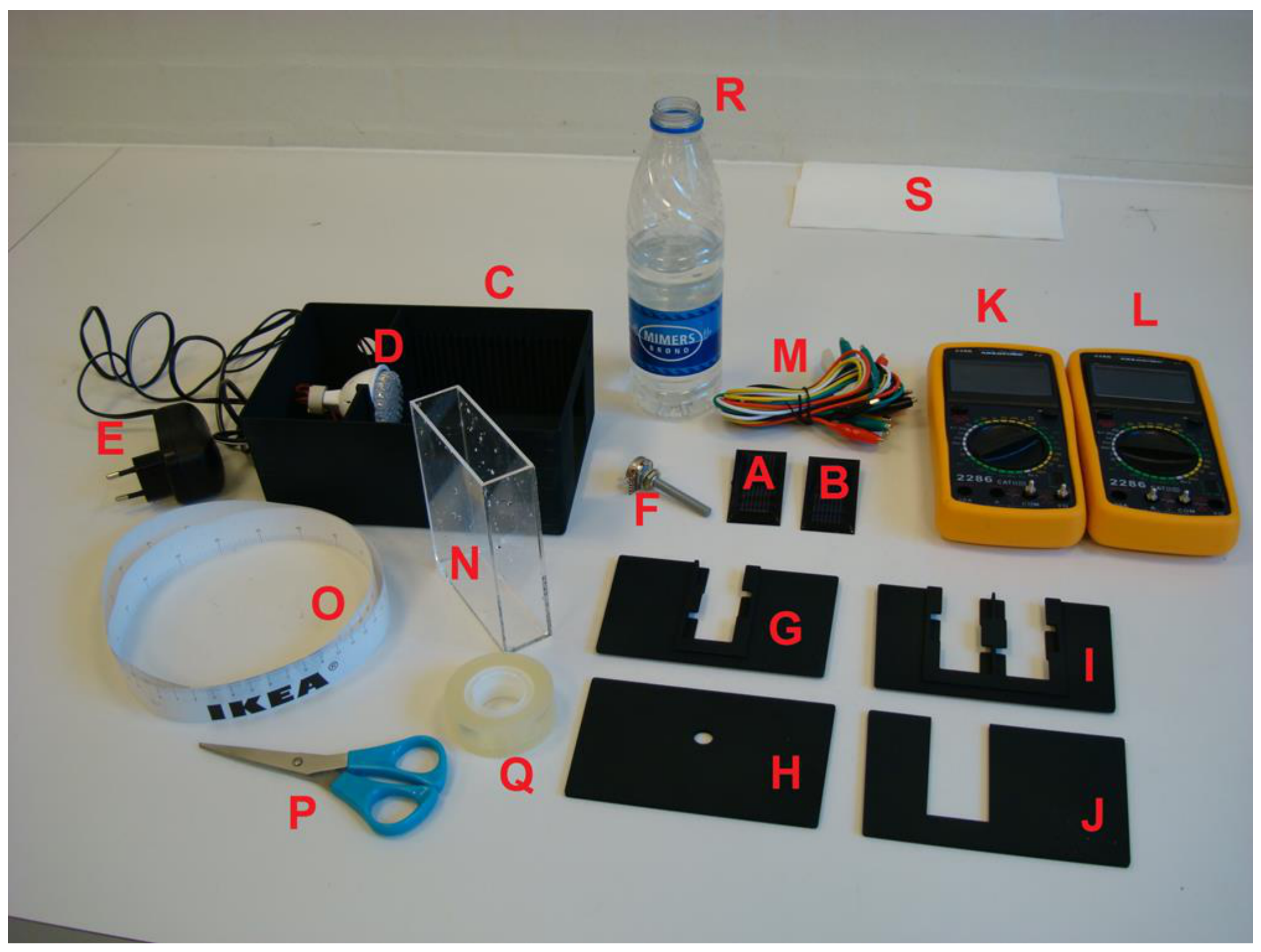
List of equipment (see Fig. 2.1):
A: Solar cell
B: Solar cell
C: Box with slots for the mounting of light source, solar cells, etc.
D: LED-light source in holder
E: Power supply for light source D
F: Variable resistor
G: Holder for mounting single solar cell in the box C
H: Circular aperture for use in the box C
I: Holder for mounting two solar cells in the box C
J: Shielding plate for use in the box C
K: Digital multimeter
L: Digital multimeter
M: Wires with mini crocodile clips
N: Optical vessel (large cuvette)
O: Measuring tape
P: Scissors
Q: Tape
R: Water for filling the optical vessel N
S: Paper napkin for drying off excess water
T: Plastic cup for water from the optical vessel N (not shown in Fig. 2.1)
U: Plastic pipette (not shown in Fig. 2.1)
V: Lid for the box C (not shown in Fig. 2.1)
Data sheet: table of fundamental constants
| Speed of light in vacuum | |
|---|---|
| Elementary charge | |
| Boltzmann’s constant |
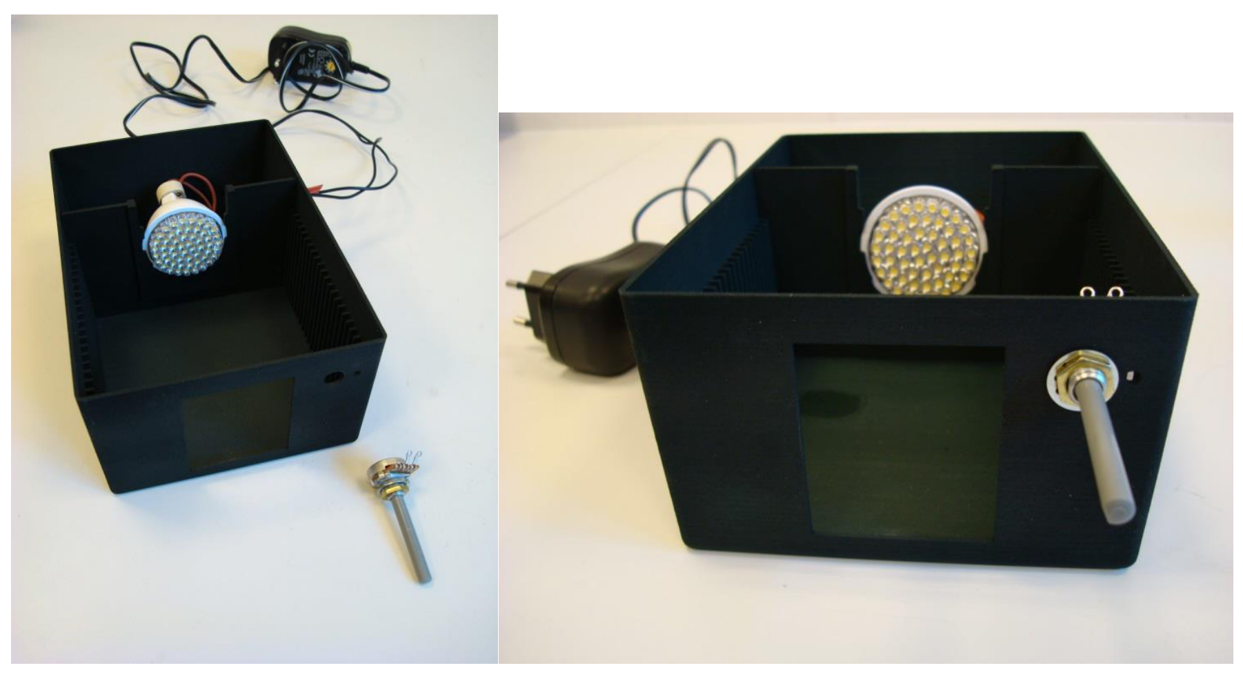
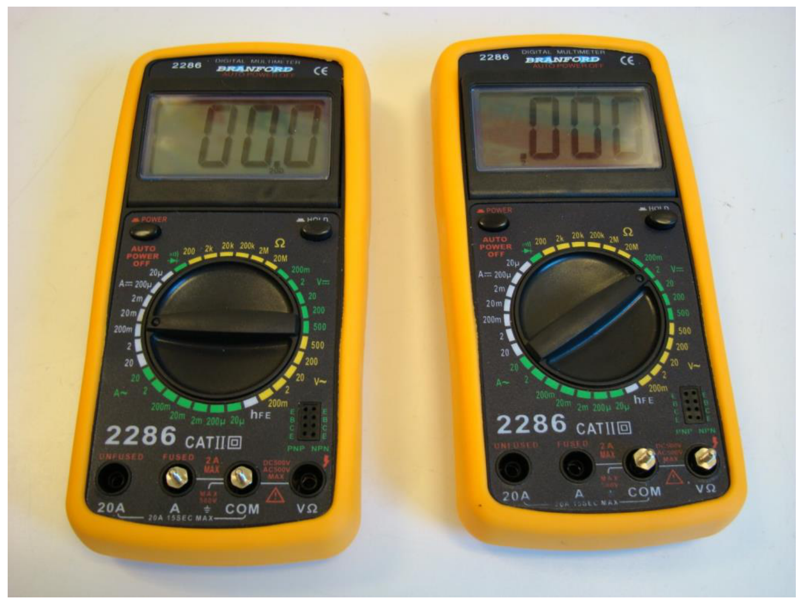
A solar cell transforms part of the electromagnetic energy in the incident light to electric energy by separating charges inside the solar cell. In this way an electric current can be generated. Experiment E2 intents to examine solar cells with the use of the supplied equipment. This equipment consists of a box with holders for light source and solar cells along with various plates and a lid. The variable resistor should be mounted in the box, see Fig. 2.2. One of the three terminals on the resistor has been removed, since only the two remaining terminals are to be used. Also supplied are wires with mini crocodile clips and two solar cells (labeled with a serial number and the letter A or B) with terminals on the back. The two solar cells are similar but can be slightly different. The two multimeters have been equipped with terminals for designated use as ammeter and voltmeter, respectively, see Fig. 2.3. Finally, the experiment will make use of an optical vessel together with some drinking water from the bottle.
2.1 The dependence of the solar cell current on the distance to the light source
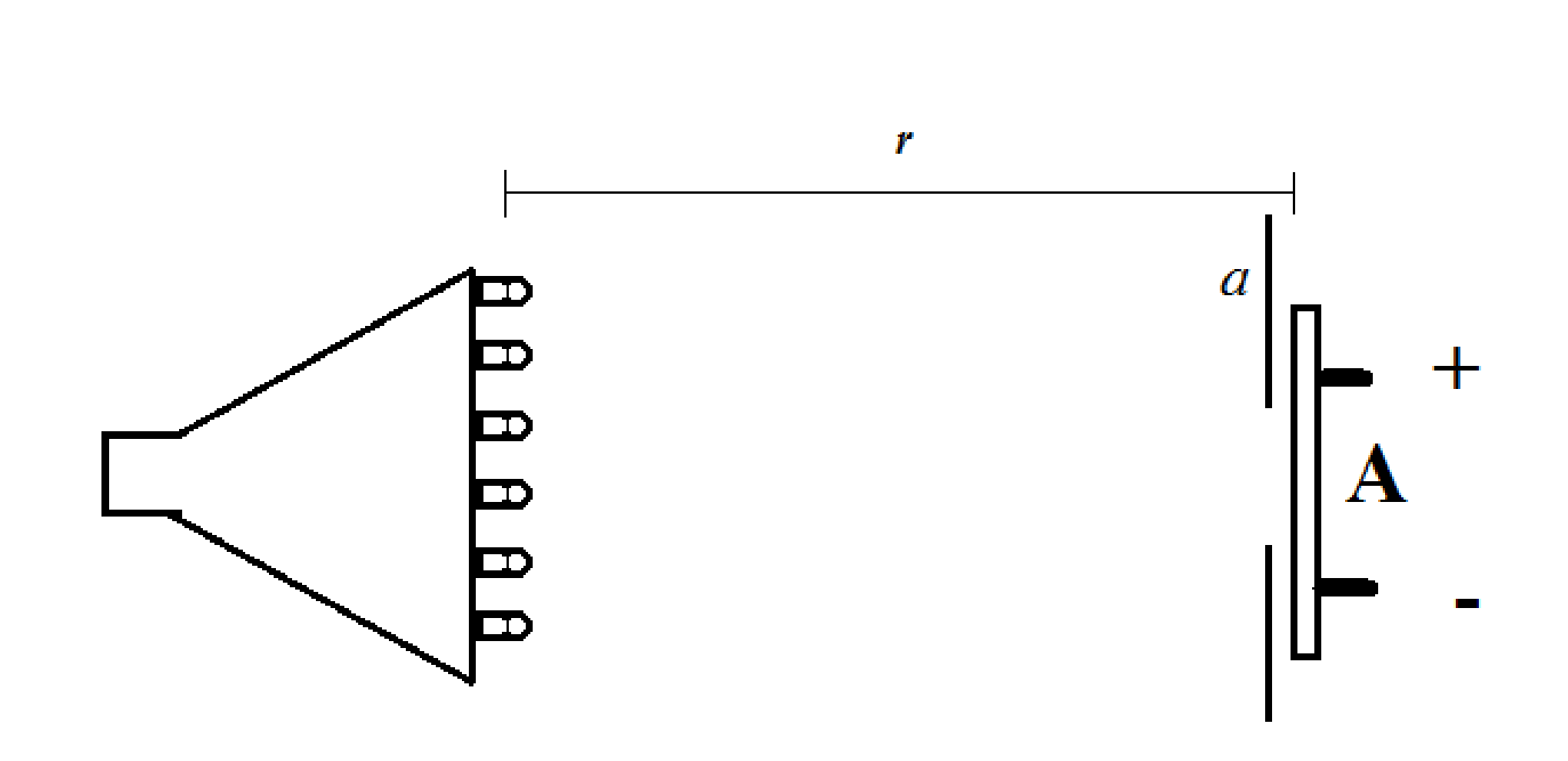
For this question you will measure the current, , generated by the solar cell when in a circuit with the ammeter, and determine how it depends on the distance, , to the light source. The light is produced inside the individual light diodes and is therefore to be measured as shown in Fig. 2.4.
Do not change the measuring range on the ammeter in this experiment: the internal resistance of the ammeter depends on the measuring range and affects the current that can be drawn from the solar cell. State the serial numbers of the light source and of solar cell A on your answer sheet. Mount the light source in the U-shaped holder (the light source has a tight fit in the holder, so be patient when mounting it. Mount solar cell A in the single holder and place it together with the circular aperture immediately in front of the solar cell. The current as a function of the distance to the light source can, when is not too small, be approximated by
where and are constants.
2.1a Measure as a function of , and set up a table of your measurements. [1 т.]
2.1b Determine the values of and by the use of a suitable graphical method. [1 т.]
Отговори
2.1b a = 35 mm ± 2 mm; Ia = 6.7 mA ± 0.5 mA
Sample measurement from the official solution; the experimental values depend on the apparatus.
Решение
| slot # | r | I | 1/I | r^2 |
|---|---|---|---|---|
| mm | mA | 1/mA | mm^2 | |
| 3 | 9.0 | 5.440 | 0.184 | 81 |
| 4 | 14.5 | 5.290 | 0.189 | 210 |
| 5 | 20.0 | 5.010 | 0.200 | 400 |
| 6 | 25.5 | 4.540 | 0.220 | 650 |
| 7 | 31.0 | 3.840 | 0.260 | 961 |
| 8 | 36.5 | 3.230 | 0.310 | 1332 |
| 9 | 42.0 | 2.730 | 0.366 | 1764 |
| 10 | 47.5 | 2.305 | 0.434 | 2256 |
| 11 | 53.0 | 1.985 | 0.504 | 2809 |
| 12 | 58.5 | 1.730 | 0.578 | 3422 |
| 13 | 64.0 | 1.485 | 0.673 | 4096 |
| 14 | 69.5 | 1.305 | 0.766 | 4830 |
| 15 | 75.0 | 1.140 | 0.877 | 5625 |
| 16 | 80.5 | 1.045 | 0.957 | 6480 |
| 17 | 86.0 | 0.930 | 1.075 | 7396 |
| 18 | 91.5 | 0.840 | 1.190 | 8372 |
| 19 | 97.0 | 0.755 | 1.325 | 9409 |
| 20 | 102.5 | 0.690 | 1.449 | 10506 |
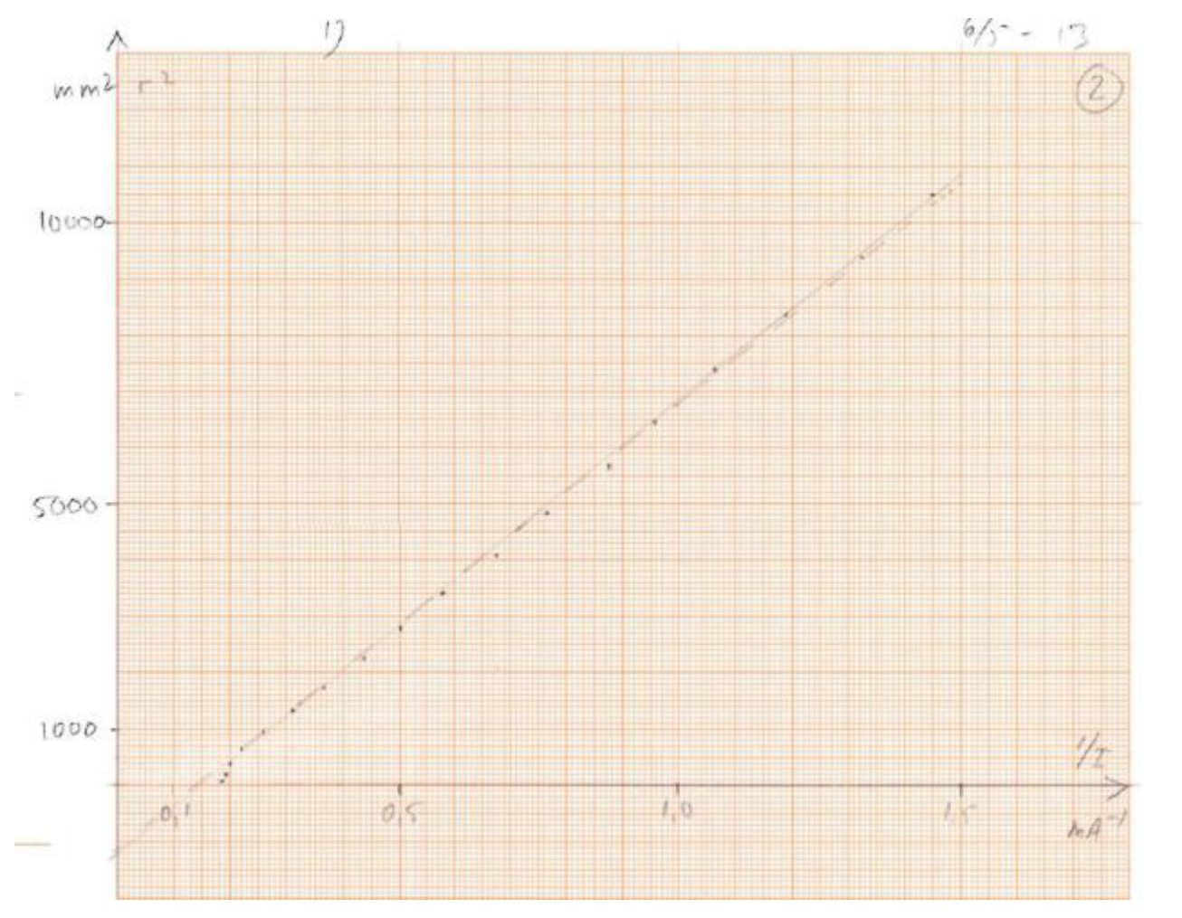
Оригинал в Архива: exp2.pdf · официални решения: exp2_sol.pdf