IPhO 2016, Теория — Задача 2. Nonlinear Dynamics in Electric Circuits
Theory · English (Official) · Q2 — Nonlinear Dynamics in Electric Circuits (10 points) · 10 т.
Условие
Please read the general instructions in the separate envelope before you start this problem.
Introduction
Bistable non-linear semiconducting elements (e.g. thyristors) are widely used in electronics as switches and generators of electromagnetic oscillations. The primary field of applications of thyristors is controlling alternating currents in power electronics, for instance rectification of AC current to DC at the megawatt scale. Bistable elements may also serve as model systems for self-organization phenomena in physics (this topic is covered in part B of the problem), biology (see part C) and other fields of modern nonlinear science.
Goals
To study instabilities and nontrivial dynamics of circuits including elements with non-linear characteristics. To discover possible applications of such circuits in engineering and in modeling of biological systems.
Part A. Stationary states and instabilities (3 points)
Fig. 1 shows the so-called S-shaped characteristics of a non-linear element . In the voltage range between (the holding voltage) and (the threshold voltage) this characteristics is multivalued. For simplicity, the graph on Fig. 1 is chosen to be piece-wise linear (each branch is a segment of a straight line). In particular, the line in the upper branch touches the origin if it is extended. This approximation gives a good description of real thyristors.
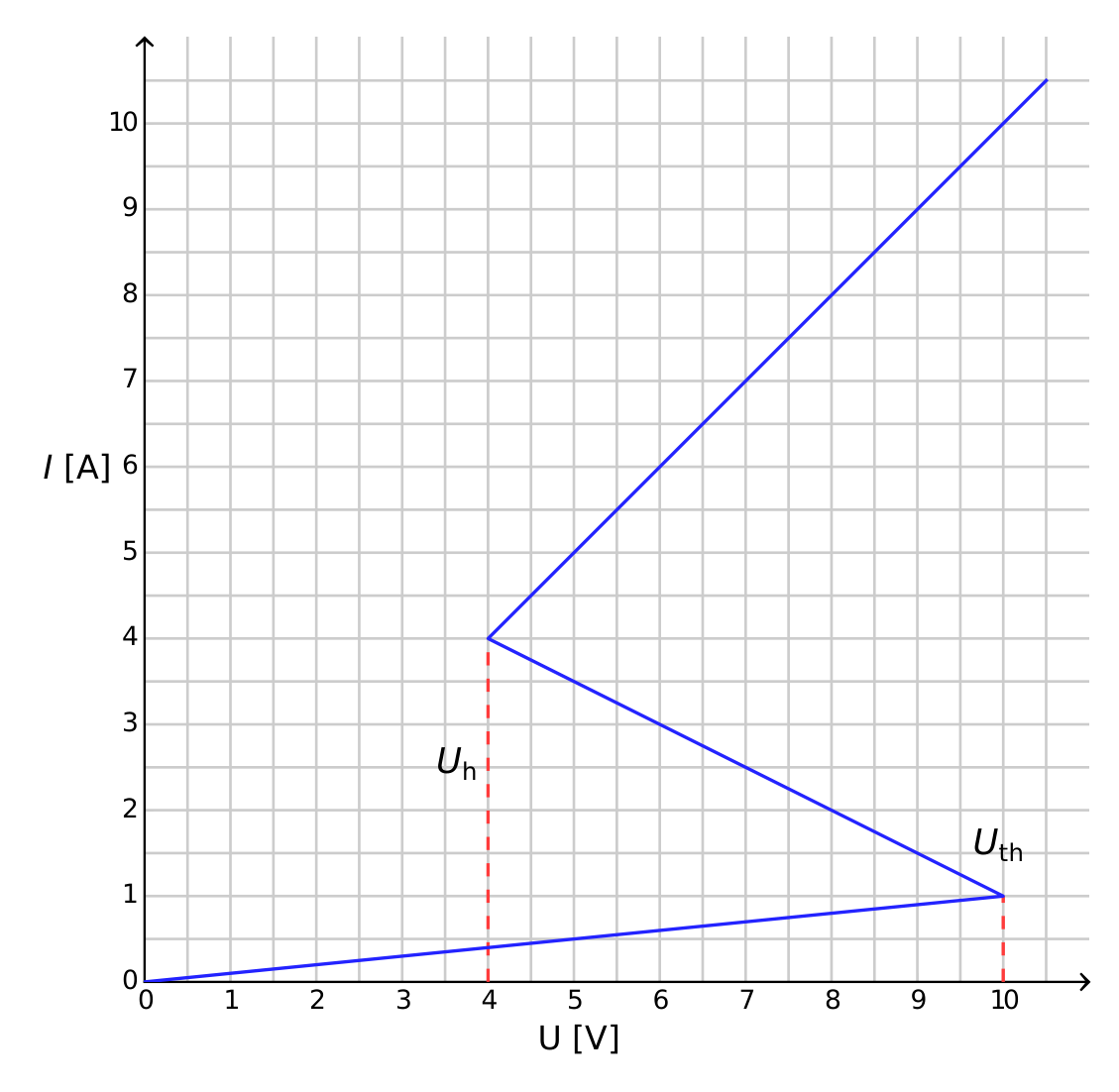
A.1 Using the graph, determine the resistance of the element on the upper branch of the characteristics, and on the lower branch, respectively. The middle branch is described by the equation
Find the values of the parameters and . [0,4 т.]
The element is connected in series (see Fig.2) with a resistor , an inductor and an ideal voltage source . One says that the circuit is in a stationary state if the current is constant in time, .
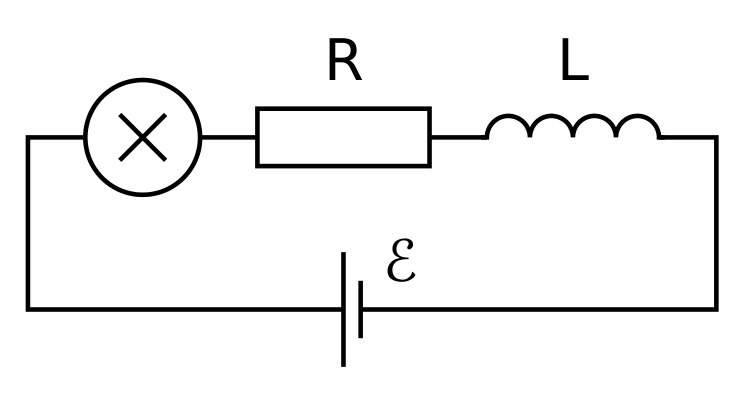
A.2 What are the possible numbers of stationary states that the circuit of Fig. 2 may have for a fixed value of and for ? How does the answer change for ? [1 т.]
A.3 Let and in the circuit shown in Fig. 2. Determine the values of the current and the voltage on the non-linear element in the stationary state. [0,6 т.]
The circuit in Fig. 2 is in the stationary state with . This stationary state is said to be stable if after a small displacement (increase or decrease in the current), the current returns towards the stationary state. And if the system keeps moving away from the stationary state, it is said to be unstable.
A.4 Use numerical values of the question A.3 and study the stability of the stationary state with . Is it stable or unstable? [1 т.]
Part B. Bistable non-linear elements in physics: radio transmitter (5 points)
We now investigate a new circuit configuration (see Fig. 3). This time, the non-linear element is connected in parallel to a capacitor of capacitance . This block is then connected in series to a resistor of resistance and an ideal constant voltage source of voltage . It turns out that this circuit undergoes oscillations with the non-linear element jumping from one branch of the characteristics to another over the course of one cycle.
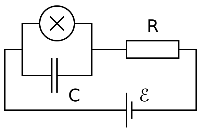
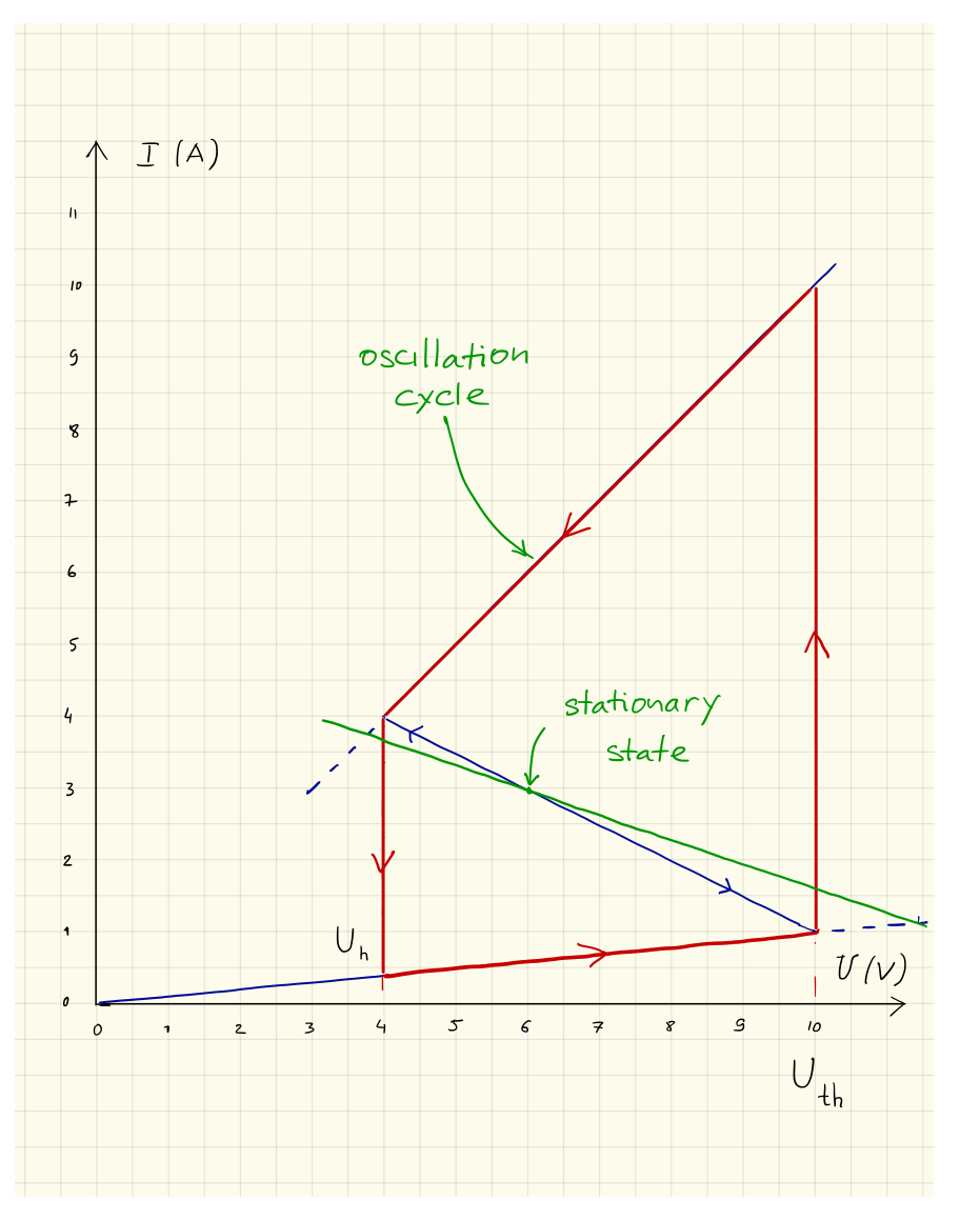
B.1 Draw the oscillation cycle on the graph, including its direction (clockwise or anticlockwise). Justify your answer with equations and sketches. [1,8 т.]
B.2 Find expressions for the times and that the system spends on each branch of the graph during the oscillation cycle. Determine their numerical values. Find the numerical value of the oscillation period assuming that the time needed for jumps between the branches of the graph is negligible. [1,9 т.]
B.3 Estimate the average power dissipated by the non-linear element over the course of one oscillation. An order of magnitude is sufficient. [0,7 т.]
The circuit in Fig. 3 is used to build a radio transmitter. For this purpose, the element is attached to one end of a linear antenna (a long straight wire) of length . The other end of the wire is free. In the antenna, an electromagnetic standing wave is formed. The speed of electromagnetic waves along the antenna is the same as in vacuum. The transmitter is using the main harmonic of the system, which has period of question B.2.
B.4 What is the optimal value of assuming that it cannot exceed ? [0,6 т.]
Part C. Bistable non-linear elements in biology: neuristor (2 points)
In this part of the problem, we consider an application of bistable non-linear elements to modeling of biological processes. A neuron in a human brain has the following property: when excited by an external signal, it makes one single oscillation and then returns to its initial state. This feature is called excitability. Due to this property, pulses can propagate in the network of coupled neurons constituting the nerve systems. A semiconductor chip designed to mimic excitability and pulse propagation is called a neuristor (from neuron and transistor).
We attempt to model a simple neuristor using a circuit that includes the non-linear element that we investigated previously. To this end, the voltage in the circuit of Fig. 3 is decreased to the value . The oscillations stop, and the system reaches its stationary state. Then, the voltage is rapidly increased back to the value , and after a period of time (with ) is set again to the value (see Fig. 4). It turns out that there is a certain critical value , and the system shows qualitatively different behavior for and for .
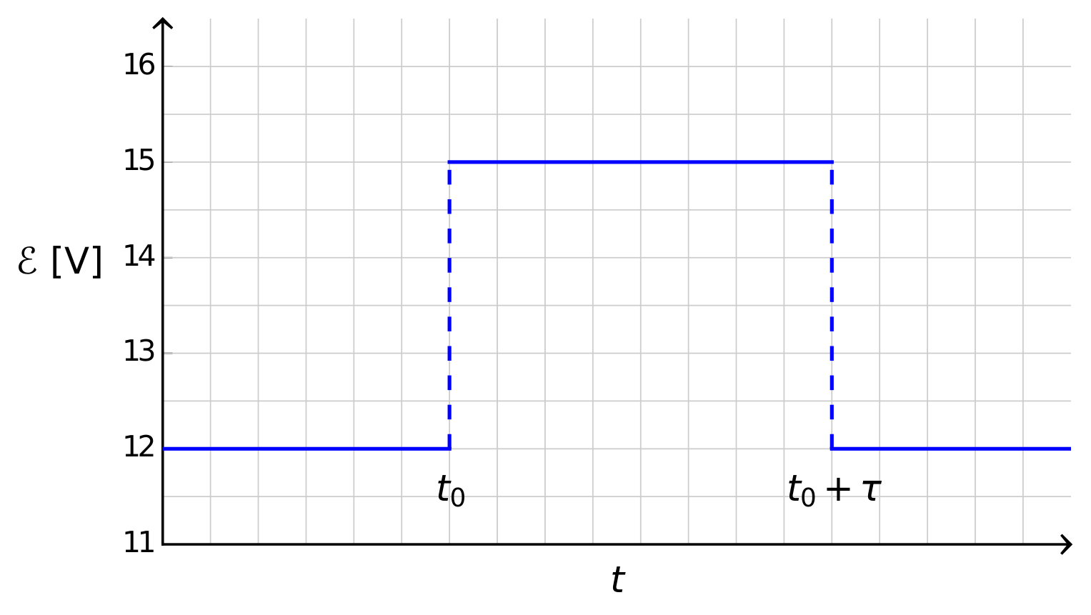
C.1 Sketch the graphs of the time dependence of the current on the non-linear element for and for . [1,2 т.]
C.2 Find the expression and the numerical value of the critical time for which the scenario switches. [0,6 т.]
C.3 Is the circuit with a neuristor? [0,2 т.]
Отговори
A.2 For R = 3.00 Ω, one always gets exactly one intersection. For R = 1.00 Ω, one gets 1, 2 or 3 intersections depending on the value of ℰ.
A.3 I_stationary = 3.00 A, U_stationary = 6.00 V
A.4 stable
B.2 ton = 2.41·10⁻⁶ s, toff = 3.71·10⁻⁶ s, T = 6.12·10⁻⁶ s
B.3 19.3 W
Order-of-magnitude estimate; the marking scheme gives full points for 5 W ≤ P ≤ 50 W.
B.4 459 m
C.2 s
C.3 Yes
Решение
Problem 2 : Solution/marking scheme – Nonlinear Dynamics in Electric Circuits (10 points)
Part A. Stationary states and instabilities (3 points)
Solution A1: [0.4]
By looking at the graph, we obtain
Note: No penalty for the number of digits in this question
Solution A2: [1]
Kirchoff law for the circuit ( is the voltage of the bistable element):
This yields
Hence, stationary states of the circuit are intersections of the line defined by this equation and the graph of . 0.2
For , one always gets exactly one intersection. 0.2
For , one gets 1, 2 or 3 intersections depending on the value of . 0.4
The following table summarizes the number of points granted for possible answers to the last subquestion with :
| Possible answer | 1 | 2 | 3 | 1,3 | 1,2 | 2,3 | 1,2,3 |
|---|---|---|---|---|---|---|---|
| Points | 0 | 0 | 0.2 | 0.3 | 0 | 0.2 | 0.4 |
Solution A3: [0.6]
The stationary state is on the intermediate branch, one can thus use the corresponding equation: 0.2
Extra (non-physical) stationary states on the switched on and/or switched off branches lead to a penalty of 0.2 point.
Solution A4: [1]
Any correct modeling such as the following: 0.5
The Kirchoff law for the circuit reads
This implies
The separation between two cases is of importance, especially because of the relative sign of :
If , we have and decreases. 0.2
If , we have and increases. 0.2
Note: Formulas with time derivatives are not essential, any other correct justification is accepted.
We conclude that the stationary state is stable. 0.1
Note: The checkbox gives 0.1 points if “stable” is checked, regardless of the previous reasoning (also if there is nothing). A wrong reasoning leading to check the “unstable” option doesn’t however give any point for the checkbox.
Part B. Bistable non-linear elements in physics and engineering: radio transmitter (5 points)
Solution B1: [1.8]
A correctly drawn cycle gives 1.2 points, distributed as follows:
- Switched on branch is part of the cycle 0.2
- Switched off branch is part of the cycle 0.2
- Jumps are vertical (constant ) 0.2
- Jumps are positioned at and 0.2
- The system moves to the left on the switched on branch 0.2
- The system moves to the right on the switched off branch 0.2
Each of the following observations individually gives up to 0.2 points, but their total cannot exceed 0.6:
- constant during jumps because the charge on the capacitor cannot change instantaneously 0.2
- The intermediate branch cannot be part of the cycle because there is a stationary state on it 0.2
- Jumps occur at corners of the IV graph because at those points the system has nowhere else to go 0.2
- The system moves moves to the left on the switched on branch because it approaches the stable stationary state (which is located outside the IV graph), or argument with the Kirchoff law 0.2
- The system moves moves to the right on the switched off branch because it approaches the stable stationary state (which is located outside the IV graph), or argument with the Kirchoff law 0.2
Solution B2: [1.9]
Since the non-linear element is oscillating between the switched on and switched off branches we can put . On either of the branches, the circuit behaves as a standard RC-circuit with conductance and resistance (the resistor and the element being connected in parallel). Another way to express it is to write the Kirchhoff law for the switched on and switched off branches 0.5
The time constant of the circuit is
If the branch in question (switched on or switched off) extended indefinitely, after a long time the system would have landed in a stationary state with the voltage
Then, the time dependence of the voltage drop on the non-linear element is a sum of the constant term and of the exponentially decaying term:
There are 0.5 points distributed as follow for :
- Correct exponential 0.2
- Correct constant term () 0.1
- Correct coefficient in front of the exponential 0.1
- Correct equation for 0.1
Time spent by the system on the switched on branch during one cycle:
Time spent by the system on the switched off branch during one cycle:
The total period of oscillations:
Note: Correct final answers give full points. One may earn points for intermediate steps (see above) for partial answers.
Solution B3: [0.7]
Neglect the energy consumed on the switched off branch. The energy consumed on the switched on branch during the cycle is estimated by
For the power, this gives an estimate of
Note:
- Formula + answer inside give full points
- Formula + answer outside the range above but inside give 0.5 points
- answer outside range but good formula gives 0.4 points
Also, the proposed formula is only an example, any other reasonable approximation of the integral of the upper branch should be accepted.
Solution B4: [0.6]
The wave length of the radio signal is given by . 0.2
The optimal length of the antenna is (or etc.) 0.3
The only choice which is below is . 0.1
Note: The correct answer gives full points, and the mistake only 0.4 pts.
Part C. Bistable non-linear elements in biology: neuristor (2 points)
Solution C1: [1.2]
For , the steady state of the system is located on the switched off branch:
When the voltage is increased to , the system starts moving to the right along the switched off branch (in the same way it did in task B).
If the voltage drops again before the system reaches the threshold voltage, it will simply return to the stationary state.
If system reaches the threshold voltage, it will jump to the switched on branch, and it will make one oscillations (since ) before the voltage drops again and it returns to the stationary state.
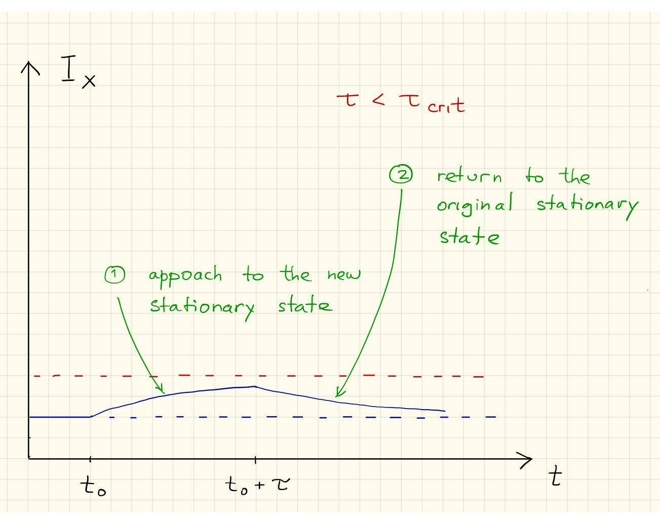
- Approach to the new stationary state 0.2
- Return to the old stationary state 0.2
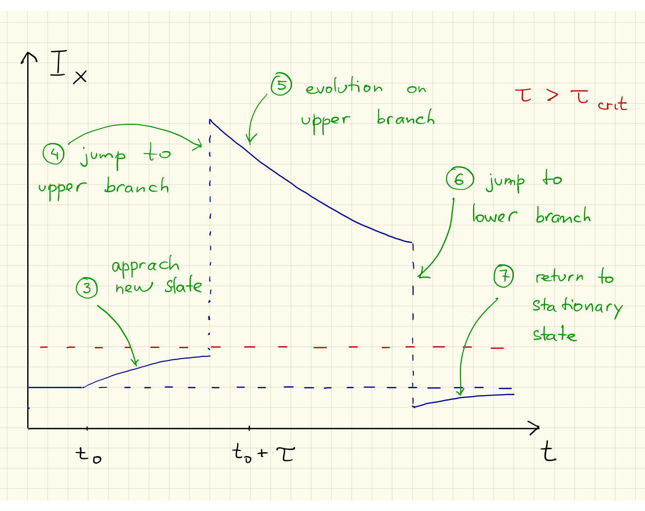
- Approach to the new stationary state 0.1
- Jump to the upper branch before 0.2
- Evolution on the upper branch 0.2
- Jump to the lower branch below the old stationary state 0.1
- Return to the old stationary state (from below) 0.2
Solution C2: [0.6]
The time needed to reach the threshold voltage is given by
Note: This is the same formula as for in task B2, with replaced by .
- Correct time constant 0.2
- Correct choice of voltages 0.2
- Correct final formula 0.1
- Correct numerical value 0.1
Note: Correct final answers give full points. One may earn points for intermediate steps (see above) for partial answers.
Solution C3: [0.2]
Since , the system will make one oscillation. We conclude that the system is a neuristor. 0.2
Note: 0.2 are given only if “Yes” is checked, regardless of the development of the other tasks.