IPhO 2019, Експеримент — Задача 1.3. Part C: The refractive index of a triangular prism
IPhO Israel 2019. Experiment Q1. Optical Measurements · 2 т.
Optical Measurements
In this experiment, we will measure the optical properties of samples at the highest achievable accuracy using the available equipment.
Note: under your table you can find 2 big water bottles that you need to use for the second experiment - do not drink them.
In part A, we will use two different methods to measure the refractive index of a transparent disk. The first method is traditional, while the second one is original and enables a higher level of accuracy.
In part B, we will measure the ratio between the laser wavelength and the lattice constant of a diffraction grating , aiming at achieving the highest possible level of accuracy.
In part C, we will measure the refractive index of a triangular prism, again – attempting to reach the highest level of accuracy.
For the experiments, the exam hall will be darkened for 100 minutes, starting 20 minutes after the exam begins (you may use a table lamp when needed). It is more convenient to perform the measurements of part A in the dark, but it is still possible to perform most of them in light as well.
You may use the walls of your cubicle as a screen, and apply adhesive tapes to the cubicle walls.
In these experiments, you are using a diode laser as a light source.
Laser safety instructions:
- NEVER look directly into the laser beam!
- In all experiments, the laser beam is horizontal. When measuring the position of the laser beam on a surface make sure your head is ALWAYS above the level of the beam.
- Do not aim the laser beam toward the opening of the experimental cubicle.
- Turn the laser off using the designated switch whenever you are not performing measurements.
Equipment list
Pieces of equipment 1-9 are used in all parts of the question, and pieces of equipment 10-12 are used in separate parts of the questions. Note that you are given multiple pieces of optical equipment - make sure not to touch their vertical sides directly, to avoid fouling their surfaces.
- Ruler, 60 cm long
- Slider that can move along the ruler
- Laser source, mounted on the slider. The laser can be set at two heights, or levels: low level 3A for part A and high level 3B for parts B and C. The on/off switch of the laser is shown in the figure as 3C
- The tension of screws 4A and 4B controls the resistance to rotation and therefore the stability of the apparatus. Use the small metal bar 4C to change the direction of the laser. Rotate 4C by 180 degrees to change the height of the laser. Do not rotate the laser around the beam axis, since the beam polarisation is pre-tuned.
- Screen: you may use the cubicle walls; you may assume the walls are perpendicular to each other
- A roll of adhesive tape which may be used to affix equipment to the table
- Flexible measuring tape
- A variety of rulers
- Table lamp
- Round transparent disk with a diameter of 20.00 cm, fixed on a protractor, which is glued to a wooden base (for part A). You should remove the 4 small wooden cubes attached to the wooden base
- Parchment paper that can be used as a transparent screen to be temporarily attached (by hand) to the side of the disk, allowing measuring the exit point without fouling the polished disk surface (for part A). It is more accurate to measure the beam exit point if you draw a line on the paper as shown in the figure.
- A wooden piece (12A) and a cylinder holder (12B) capable of rotating along its vertical axis, for mounting the diffraction grating (12C) or the triangular prism (12D)
Photographs of the equipment are shown with Part A.
Условие
You are given an approximately equilateral, triangular prism. The three faces of the prism are planar and highly polished. The angles of the prism might deviate from but by no more than . You don't need to measure the angles of the prism. The goal of this section is to measure the refractive index of the material the prism is made of. To reduce the error in the refractive index, it is possible, by using the small angle approximation (, when is measured in radians) to correct for the small deviations in the prism’s angles. In this section you are required to make error calculations. The figures shows an example of a ray entering the prism through one face and exiting through the next one.
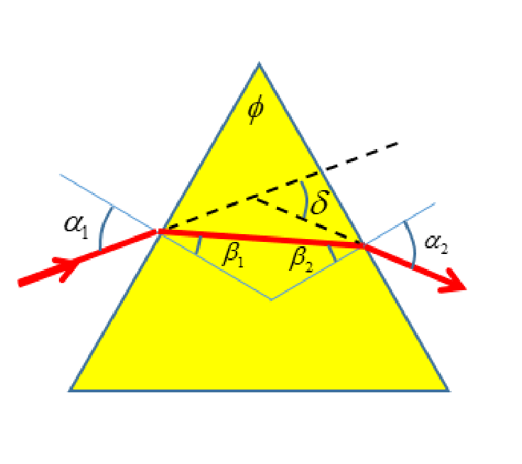
Place the slide ruler at a suitable place on the table so that the laser will allow you to achieve the highest accuracy in the measurements.
Place the prism in the designated holder 12B.
C.1 In the symmetric case, , the following relation holds for an equilateral prism: .
- Develop a method that would allow you to find the prism's refractive index with the highest accuracy.
- Detail in the answer sheets the formulas you are using to find the refractive index. [0,4 т.]
C.2 - Record in the answer sheets the quantities you have measured and their values (including errors).
- Calculate the refractive index of the prism for the wavelength of the laser, and the error in that value. [1,6 т.]
Отговори
C.1
C.2 1.6433
n = 1.6433 ± 0.0006; the literature value is 1.6425 ± 0.0007.
Решение
Section C – the refraction index of a triangular prism
C.1: From the sketch showing the path of the laser beam and from the principle the beam path reversal we get that the deflection angle from the direction of in the incoming beam will not change if we switch the angles and . Thus we get that achieves an extremum value (in fact, a minimal value) when the situation is perfectly symmetric, that is when . In this case,
.
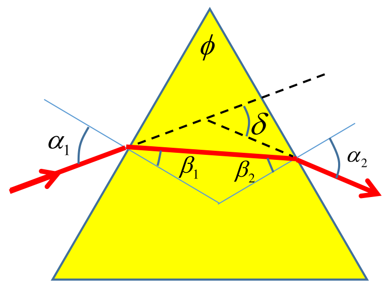
For the symmetric case, the incident angle holds the relation and from Snell’s law we get .
If the prism is not exactly equilateral, we will mark the angles of the prism by . From the sum of angles in a triangle we get . Additionally . In this case where is the minimal when .
From Snell’s law we get . Making the small angle approximation:
From the equation that holds for prism we get
Averaging for all three angles we get , and therefore
C.2. We will use the full length of the table to magnify the distances as much as possible. We will build the setup, as described in the sketch, so that in the absence of the prism, the laser beam will hit the screen (the chamber’s wall) perpendicularly. We will attach the prism holder base to the table using the adhesive tape. On it we will place the prism holder and the prism itself. We will rotate the prism to find the minimal deflection angle . We will then repeat the measurement of for each corner of the prism.
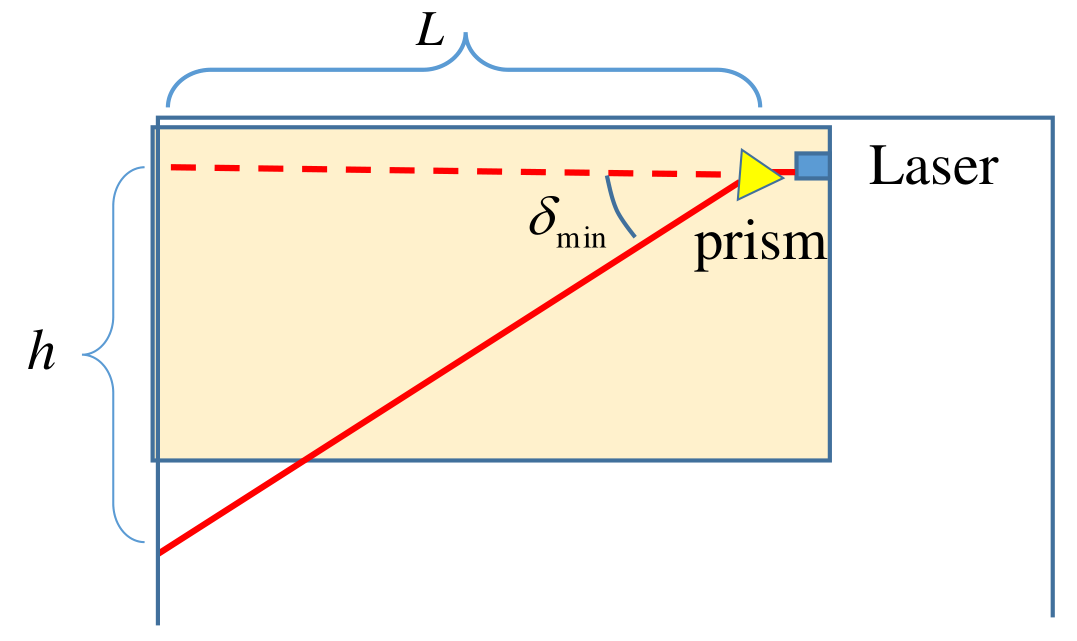
The measured values are given in the table:
| Corner No. | |||
|---|---|---|---|
| 1 | |||
| 2 | |||
| 3 |
Calculation of the error in :
Therefore,
Substituting the measured values we get
The error in the average value of the two angles is
From the table we get that the average value of is
Therefore the refraction index of the prism is
And the error in :
Thus:
As the laser wavelength may vary between lasers up to a standard deviation of , the value found in the literature is .
Оригинал в Архива: exp1.pdf · официални решения: exp1_sol.pdf