IPhO 2023, experiment — Задача 1. Mass Measurement
Автор: Olympiads XYZ · транскрипция на официалните материали
Проверена срещу оригинала на 13.9.2026 от същия модел, който я е транскрибирал (без независима проверка)
Experiment — IPhO International Physics Olympiad 2023 Tokyo Japan — Mass Measurement (10 points) · 10 юли 2023 г. · 10 т.
Внимание: Бележка към темата
This window covers only problems pages 6–9; the problem statement begins on an earlier page.
Условие
In this experimental problem, a measurement of mass is attempted. We further measure the mass utilizing the resonance characteristics of the harmonic oscillator.
Experimental setup
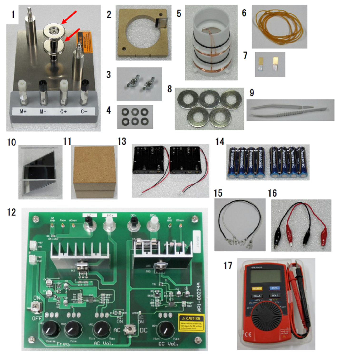
Below is the list of parts (Fig. 1). The number of the parts is given in [] if only there are two or more.
Mounting base:
Note: magnet unit on the base creates the height-independent uniform radial magnetic fields warranted near the center of the magnet pair to within mm in height.
(Oscillator) support
Thumbscrews [2]:
Note: Remove 2 and 3 from 1 in the as-received package for use.
Shim (washer) [6]
Cylindrical oscillator
Rubber bands [6]
Markers [2]
Weights [5]
Tweezers
Mirror
Riser block
Power supply (PS):
DC or AC mode is toggled on.
In the DC mode, it works as the constant-current source. Turn the knob labeled “DC Vol” to adjust the current. The magnitude of current is obtained from the voltage between “DCmon” and “DC GND” using the conversion factor 1.00 A/V.
In the AC mode, it functions as the voltage source with a fixed amplitude. Turn the “AC Vol” to adjust the voltage. The AC current is obtained from the AC voltage between “ACmon” and “AC GND” using the conversion factor 0.106 A/V. The frequency (Freq.) is tunable by using the “Coarse” and “Fine” tuning knobs.
Battery holders [2]
Batteries [8]
U-shaped crimp terminal wires [2]
Alligator clip wires [2]
Digital multimeter (DMM):
Turn the knob to select an appropriate measurement mode, "DCV", "ACV", and "Hz". Note that the displayed value of the AC voltage indicates the root mean square (RMS) value, i.e., the effective value.
Modeling the system
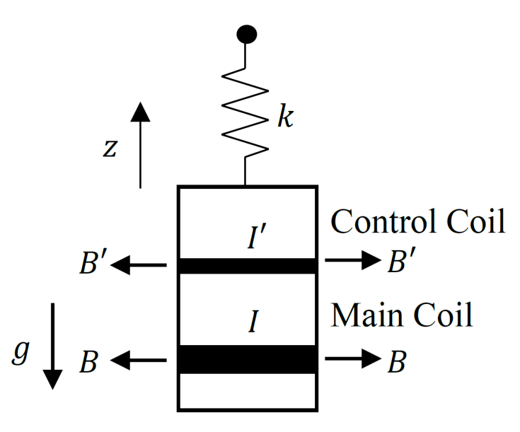
Figure 2 is a simplified model of the experimental setup. It is essentially a driven mass-on-spring oscillator.
The relevant parameters are:
- : mass of the (cylindrical) oscillator
- : mass per weight
- : the number of weights
- : acceleration due to gravity
- : effective spring constant pertaining to the vertical motion
- : oscillator height (or displacement)
- : oscillator height at which a force balance without gravitational and electromagnetic forces is established.
- (): magnetic field applied to the main (control) coil
- (): length of the conducting wire of the main (control) coil
- (): current flowing through the main (control) coil
- : positive coefficient of drag force
The equation of motion is given by
Installation of the oscillator
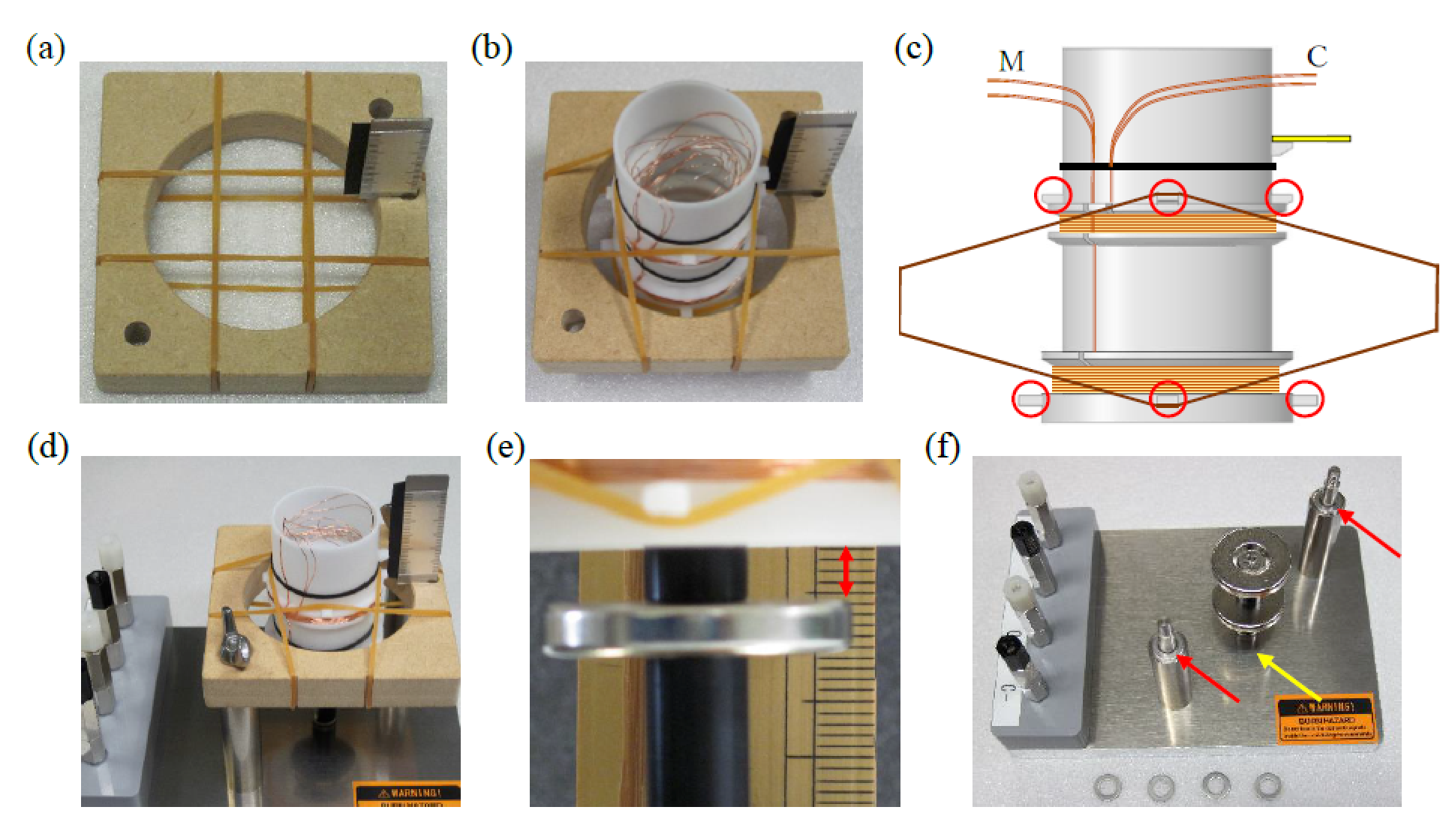
Remove the support from the mounting base. Wrap four rubber bands around it in a grid pattern (See Fig. 3(a)).
Insert the cylindrical oscillator from the scale side into the square opening amid the crossed rubber bands. Place the wire leads on the other side of the scale. (Fig. 3(b)).
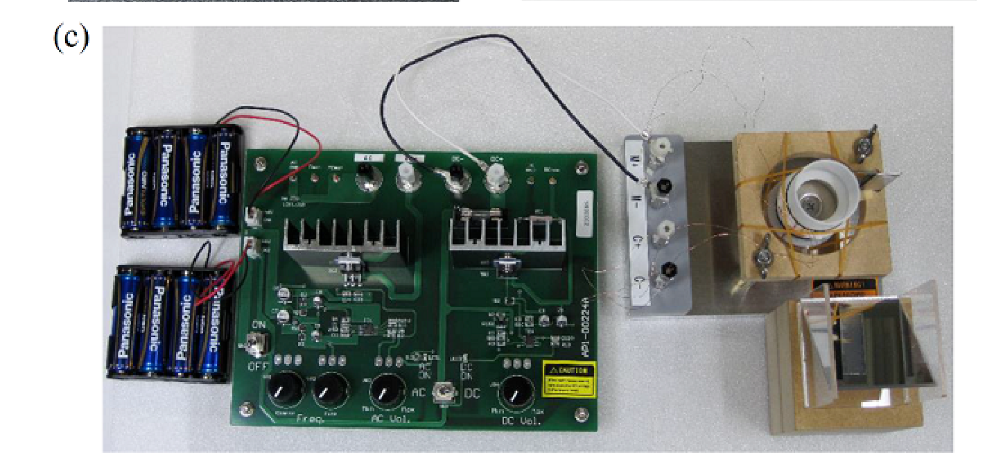
The oscillator is designed to hang on the support with four rubber bands and eight little hooks (red circled in Fig. 3(c)). When properly implemented, one rubber band loop forms a truncated rhombus with two hooks above and below the support level in the side view.
Note: In this experiment, we can assume that the effective force due to the rubber bands obeys Hooke's law.
Refix the support to the post diagonally with two thumbscrews. The scale has to stand upright on top, not on the side of the binding posts (Fig. 3(d)).
Stand the oscillator upright. Its axis must be aligned vertically and shared with the magnet unit.
The main coil should sit near the middle of the two magnets when at rest, which can be confirmed by the distance between the upper surface of the lower magnet and the lower surface of the oscillator being 3 to 5 mm (Fig. 3(e) red arrow). If it is low, put the shims between the binding posts and the support (Fig. 3(f) red arrows). If it is high, turn the post of the magnet to remove it and add the shim under the post (Fig. 3(f) yellow arrow).
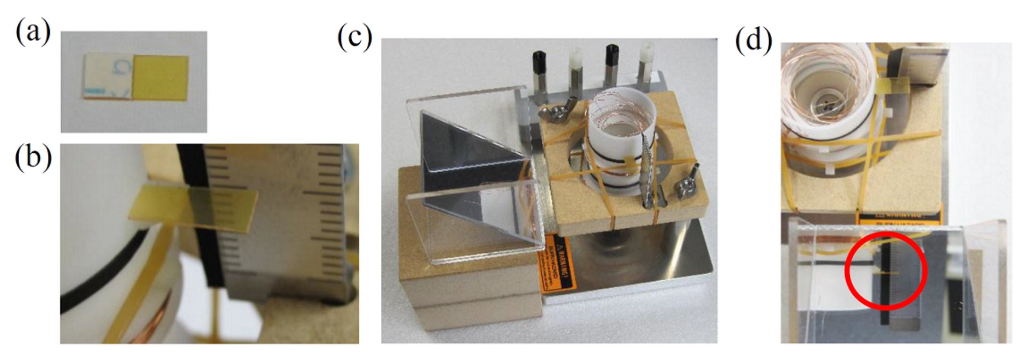
Expose the sticky surface of the double-sided adhesive tape on the marker (Fig. 4(a)). Glue the marker to the tiny little floating shelf on the oscillator to measure the height (Fig. 4(b)).
Set the mirror on the riser block (Fig. 4(c)). Secure a clear vision of the marker from above through the mirror (Fig. 4(d) red circle).
Wiring
- Locate and pull gently the correct pair of wires leading to the main (M) and control (C) coils (Fig. 3(c)) from inside the oscillator (Fig.3(b)). Check to see if the enamel has been stripped off from the loose ends.
- Loosen the screw on the binding posts M+ and M- to allow for gaps. Use the lower gaps for the wiring (Fig. 5(a), (b)). The polarity check will follow soon.
- Wire the binding posts labeled C+ and C- likewise. (Either polarity is acceptable.)
- Place the batteries in the battery holders and secure connections with PS (CN1, CN2) (Fig. 5(c)).
- Connect the binding posts M+ and M- to the DC output (DC+ and DC-) on PS using the U-shaped crimp terminal wires.
- Toggle on DC and power up PS.
- Turn the “DC Vol.” knob to adjust the current. Check to see if the oscillator moves upward by 2 mm or higher. If downward, swap the wires for polarity reversal and try again.
Caution: Hot parts. Beware of coils and magnets. Put the DC output down to the minimum at the end of each step.
Oscillator test
- Connect the M+ and M- binding posts to the AC output (AC+ and AC-) with the crimp terminal wires.
- Toggle on the AC and power up PS.
- Turn the knob labeled “AC Vol.” clockwise starting from the minimum up to a quarter turn. Tune the frequency with the “Coarse” control knob to start oscillation.
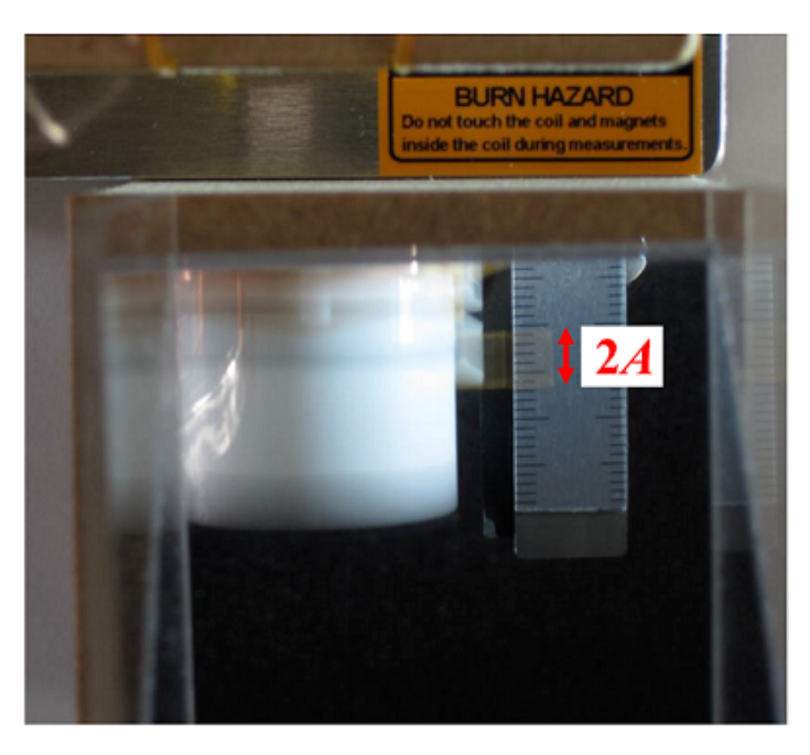
- Adjust the AC output voltage and frequency to make the oscillation about mm in amplitude (Fig.6). If the oscillation is unstable, adjust the oscillator settings as appropriate.
- Disconnect M+ and M- and connect the C+ and C- binding posts to the AC output.
- Power up PS to start oscillation again.
Part A. Hooke's law and electromagnetic forces (2.4 points)
A.1 (0.4 pt) Draw in the answer sheet the magnetic field lines created by the two identical disc-shaped magnets with their N poles facing each other.
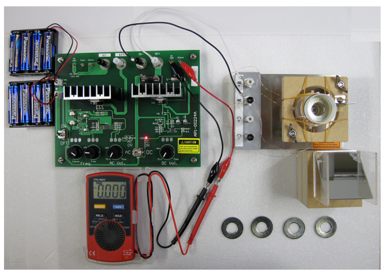
A.2 (0.6 pt) Connect the M+ and M- posts to the DC output. Couple the DMM with the terminals for DC current readouts using the alligator clip wires (Fig. 7). Read the oscillator height at null DC current without a weight, i.e., . Record it in Table A.2. Place a weight () on a circular shelf hanging out from the inner wall of the cylinder and record the height at which the oscillator comes to rest. What is the DC current flowing through the main coil to bring the oscillator back to where it was without a weight? Repeat the measurements with increasing up to 5 to fill in Table A.2.
A.3 (0.7 pt) Draw a graph showing the relationship between the number of the weights and the height . Obtain the slope and its uncertainty from the graph.
A.4 (0.7 pt) Draw a graph showing the relationship between the number of weights and the current . Obtain the value of defined as and its uncertainty from the graph.
Part B. Induced electromotive force (3.0 points)
B.1 (0.2 pt) Suppose that an AC current at frequency is applied to the control coil without a weight. Given that the oscillator height varies sinusoidally with time
where is the height for the force balance and is the amplitude of the oscillation, write down the expression for the amplitude of the induced electromotive force in the main coil.
B.2 (0.5 pt) Connect the C+ and C- posts to the AC output. Connect the DMM to the "Fmon" and "AC GND" to read the frequency. Adjust both the AC frequency and the output voltage to produce a steady oscillation of appropriate amplitude. Measure the frequency and record it in the answer sheet. Couple the DMM with the binding posts M+ and M-. With the frequency fixed, vary the output voltage and measure the oscillation amplitude and the AC voltage () induced in the main coil. Fill in Table B.2 as appropriate.
B.3 (0.7 pt) Draw a graph showing the relationship between the amplitude and voltage . Obtain the value of defined as and its uncertainty from the graph.
B.4 (0.4 pt) Calculate and its uncertainty using the results of B.3.
B.5 (1.2 pt) Using the results of A.3, A.4, and B.4, calculate the values of and and quantify their uncertainties. Use the acceleration due to gravity, where appropriate.
Part C. Mass-dependent resonant frequency (2.3 points)
For the following experiments use the main coil to drive the oscillator. Change connections accordingly.
C.1 (0.2 pt) Write down the expression for the resonant frequency of the oscillator with weights. Use the spring constant during motion, which is different than .
C.2 (0.5 pt) Drive the oscillator by coupling AC power to the main coil. Measure the resonant frequency , for different number of weights, to 5, and write down the values in Table C.2. Avoid jumping weights.
C.3 (1.0 pt) Using the results of C.2, draw a graph to obtain and . Write down the obtained values in the answer sheet. If you need to calculate any additional physical quantities, write them down in the blanks of Table C.2.
C.4 (0.6 pt) What is the value of ? Calculate and using the results of B.5.
Part D. Resonance characteristics (2.3 points)
When a periodic force of amplitude and frequency acts on the oscillator without a weight, the oscillation amplitude of is well described by the following with resonance characteristics:
Here . This equation only holds in the frequency range where is relevant.
In this part, the resonance characteristics are used to obtain the mass of the oscillator, , assuming that Eq. (3) is always valid.
D.1 (0.4 pt) Drive the oscillator by coupling AC power to the main coil. Adjust the frequency and output voltage to produce a resonance with appropriate amplitude. Record the AC voltage between the "ACmon" and "AC GND" in the answer sheet. Using the results of B.4 and the conversion factor 0.106 A/V, calculate the amplitude of the periodic electromagnetic force acting on the oscillator.
D.2 (0.9 pt) Record in Table D.2 the amplitude of the oscillation as the frequency is varied. A constant amplitude of the applied force must be maintained throughout the measurement. Draw a graph showing the relationship between the frequency and the amplitude .
D.3 (1.0 pt) Using the results of D.1 and D.2, obtain .
A.1 Draw in the answer sheet the magnetic field lines created by the two identical disc-shaped magnets with their N poles facing each other. [0,4 т.]
A.2 Connect the M+ and M- posts to the DC output. Couple the DMM with the terminals for DC current readouts using the alligator clip wires (Fig. 7). Read the oscillator height at null DC current without a weight, i.e., . Record it in Table A.2. Place a weight () on a circular shelf hanging out from the inner wall of the cylinder and record the height at which the oscillator comes to rest. What is the DC current flowing through the main coil to bring the oscillator back to where it was without a weight? Repeat the measurements with increasing up to 5 to fill in Table A.2. [0,6 т.]
A.3 Draw a graph showing the relationship between the number of the weights and the height . Obtain the slope and its uncertainty from the graph. [0,7 т.]
A.4 Draw a graph showing the relationship between the number of weights and the current . Obtain the value of defined as and its uncertainty from the graph. [0,7 т.]
B.1 Suppose that an AC current at frequency is applied to the control coil without a weight. Given that the oscillator height varies sinusoidally with time
where is the height for the force balance and is the amplitude of the oscillation, write down the expression for the amplitude of the induced electromotive force in the main coil. [0,2 т.]
B.2 Connect the C+ and C- posts to the AC output. Connect the DMM to the “Fmon” and “AC GND” to read the frequency. Adjust both the AC frequency and the output voltage to produce a steady oscillation of appropriate amplitude. Measure the frequency and record it in the answer sheet. Couple the DMM with the binding posts M+ and M-. With the frequency fixed, vary the output voltage and measure the oscillation amplitude and the AC voltage () induced in the main coil. Fill in Table B.2 as appropriate. [0,5 т.]
B.3 Draw a graph showing the relationship between the amplitude and voltage . Obtain the value of defined as and its uncertainty from the graph. [0,7 т.]
B.4 Calculate and its uncertainty using the results of B.3. [0,4 т.]
B.5 Using the results of A.3, A.4, and B.4, calculate the values of and and quantify their uncertainties. Use the acceleration due to gravity, where appropriate. [1,2 т.]
C.1 Write down the expression for the resonant frequency of the oscillator with weights. Use the spring constant during motion, which is different than . [0,2 т.]
C.2 Drive the oscillator by coupling AC power to the main coil. Measure the resonant frequency , for different number of weights, to 5, and write down the values in Table C.2. Avoid jumping weights. [0,5 т.]
C.3 Using the results of C.2, draw a graph to obtain and . Write down the obtained values in the answer sheet. If you need to calculate any additional physical quantities, write them down in the blanks of Table C.2. [1 т.]
C.4 What is the value of ? Calculate and using the results of B.5. [0,6 т.]
D.1 Drive the oscillator by coupling AC power to the main coil. Adjust the frequency and output voltage to produce a resonance with appropriate amplitude. Record the AC voltage between the “ACmon” and "AC GND" in the answer sheet. Using the results of B.4 and the conversion factor 0.106 A/V, calculate the amplitude of the periodic electromagnetic force acting on the oscillator. [0,4 т.]
D.2 Record in Table D.2 the amplitude of the oscillation as the frequency is varied. A constant amplitude of the applied force must be maintained throughout the measurement. Draw a graph showing the relationship between the frequency and the amplitude . [0,9 т.]
D.3 Using the results of D.1 and D.2, obtain . [1 т.]
Решение
Покажи официалното решение
Оригинал в Архива: IPhO_2023_Q4.pdf · официални решения: IPhO_2023_S4.pdf