Съдържание
Before the TestDuring the examAt the end of the examSpecific instructionsУсловиеOverview of the Experimental SetupExperimental EquipmentMain Apparatus (see Fig.2)Electronic Module (see Fig.3)Hydraulic Module (see Fig.6)Pump and Valve OperationAdditional ItemsImportant Operating NotesConstants and Reference ValuesPart A. Isochoric (isovolumetric) process of an ideal gas (4 т.)ProcedurePart B. Vapor Pressure (8 т.)ProcedurePart C. Heat Conduction (8 т.)ProcedureРешениеIPhO 2026, Експеримент — Задача 1. Ideal Gas, Vapor Pressure, and Heat Conduction
Ideal Gas, Vapor Pressure, and Heat Conduction · 20 т.
Внимание: Бележка към темата
The archived question sheet and official key are different revisions: A1–A3 are reordered and several marks differ. Both are preserved under their printed labels. The key prints m = 0.94 g beside V = 85 mL, which disagrees with the question’s density; its C6 slope, graph and RTh = c₀ma expression disagree. C7 prints an extra T in one denominator, a missing pair of parentheses and differing uncertainty notation. These source expressions are retained, not silently corrected. The separate blank answer and working sheets mentioned in the instructions are absent from this archive folder.
General Instructions
Experimental exam (20 points), July 6, 2026.
Failure to comply with any of the following rules may result in disqualification. The experimental exam lasts 5 hours and is worth a total of 20 points. The beginning and end of the exam will be indicated by an announcement, as well as every hour, indicating the time elapsed. This will also be done thirty, fifteen and five minutes before the end of the exam.
Before the Test
Do not open the envelopes or boxes until instructed. The following items are provided for use at the table: (1) a pen, (2) a scientific calculator.
During the exam
- Use the supplied pen to answer the questions.
- Use the A-sheets for your final answers. Fill in the appropriate sections with your answers and necessary observations. Draw the necessary graphs.
- Blank worksheets labeled with the letter W are provided for calculations. Use designated ones. Cross off unnecessary answers and drafts that shouldn't be graded with an X. Use only the front of each sheet and keep the margin off the edge clean. The back side of the pages will not be scanned and their contents will not be considered
- Answers should be concise and readable. Use equations, logic operators, symbols, and schematics to express your ideas clearly. Avoid using explanatory texts, as markers may not be multilingual.
- Quantify uncertainty, unless otherwise noted. You must decide how many data points or series of measurements are necessary, unless otherwise specified.
- Do not leave your post without permission. If you need any help (going to the bathroom, getting water, etc.), lift the paddle with the "Help" sign.
At the end of the exam
- Stop writing immediately when the end of the exam is announced.
- Place all the sheets in the envelope provided. Arrange them face up in this order: General Instructions, Question Sheets (Q), Answer Sheets (A), Worksheets (W). Sort by page number.
- The supervisors will tell you when you can leave. Don't take anything from the room with you, including the the calculator.
We appreciate your collaboration.
Specific instructions
Throughout the exam, always use the values of physical constants indicated in the instructions, unless otherwise noted. When performing a series of measurements, explicitly indicate in the tables the measured values and the values represented in the graphs. Be attentive to write down the appropriate significant digits. All graphs should clearly show the quantities involved. Always indicate the units of all values used.
Условие
In this experimental exam, you will study three physical phenomena: the behavior of an ideal gas, the vapor pressure of water, and heat transfer by conduction. The objective of the exam is to analyze the relationships between pressure , air volume , temperature , and time , present your results in relevant graphs, and estimate associated physical constants and their associated uncertainties.
Overview of the Experimental Setup
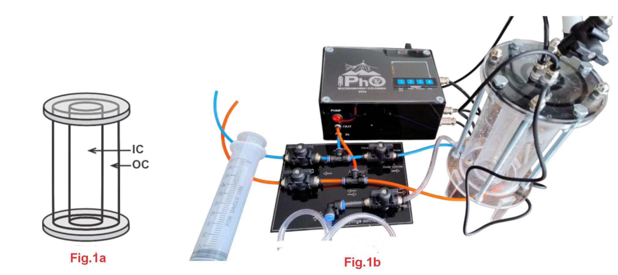
Before beginning the experiment, read the assembly description, list of materials, general instructions, and procedure for each part of the test.
The apparatus consists of two concentric cylinders made of acrylic (Fig.1a). The inner cylinder (hereafter IC) can contain air and liquids, and the air inside IC is referred to as confined air (hereafter CA). The amount of liquid in the IC can be controlled by connecting the syringe to hose D.
The outer cylinder (hereafter OC) can only be filled with water and acts as a thermal jacket. Its water level can be adjusted using inlet and outlet hoses and valves, while its temperature is controlled by an electric heater. Two sensors are installed inside the IC: one for pressure and one for temperature. A separate temperature sensor is available in the OC.
Experimental Equipment
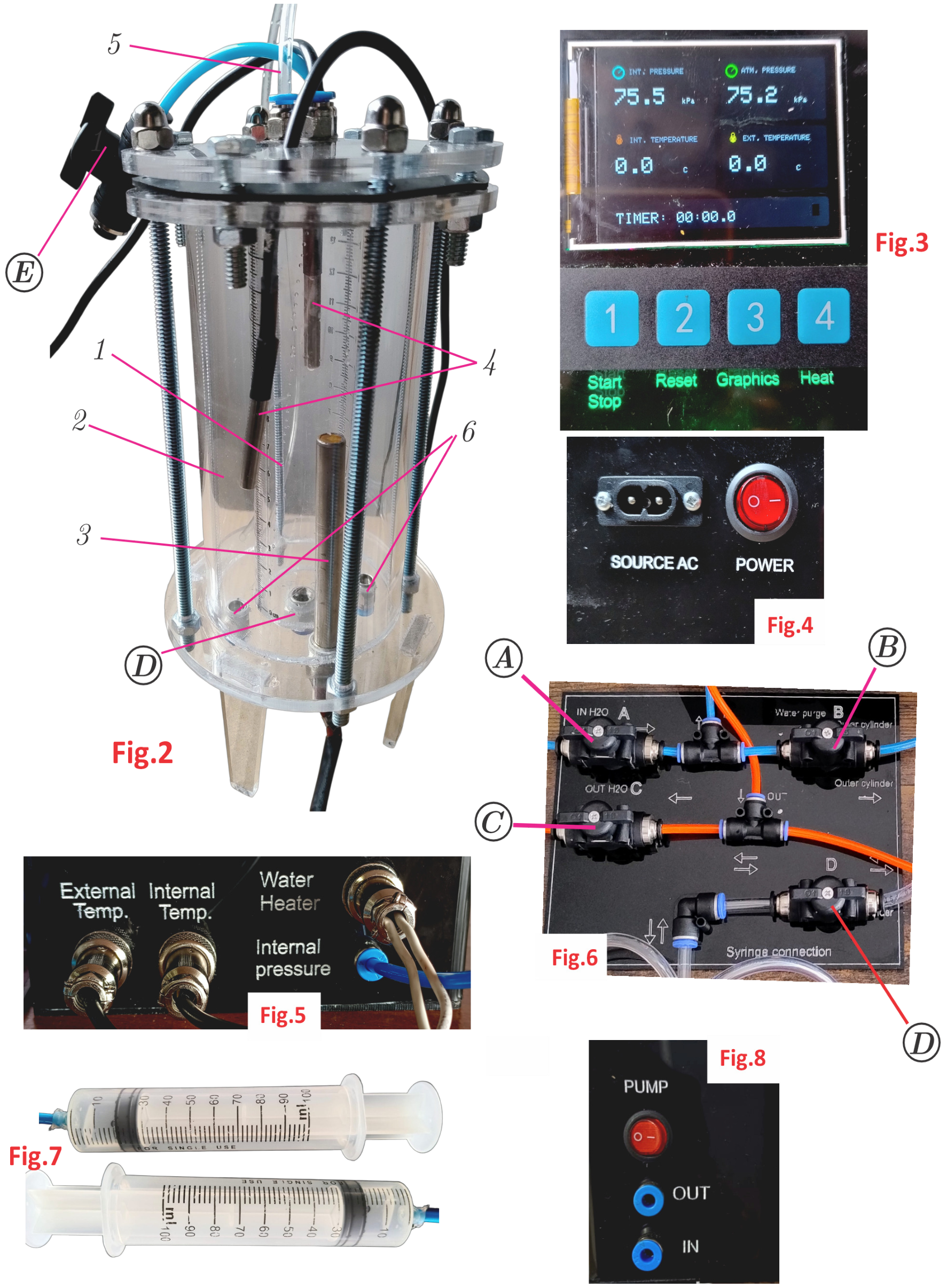
Main Apparatus (see Fig.2)
- Inner cylinder (IC): Graduated with two centimeter scales. Its fixed lids keep the contents airtight.
- Outer cylinder (OC): Acts as a thermal jacket.
- Heater: Installed in the OC and powered by the electronic module.
- Temperature sensors: Two sensors, connected to the electronic module by black wires, measure the temperature in each cylinder.
- Pressure sensor hose: Connects CA to a pressure sensor hosted in the electronic module, allowing measurement of the internal pressure.
- OC water connections: Two hoses provide water with an inlet to and outlet from the OC.
Valve E — IC atmospheric connection: Opens or closes the connection between the IC and the atmosphere.
Electronic Module (see Fig.3)
The electronic module must be connected to the main power before use. The power switch, labeled Power, is located at the back of the module (Fig.4).
The digital display provides the following readings:
- Internal pressure: Pressure inside the IC (INT. PRESSURE).
- Atmospheric pressure: Local atmospheric pressure (ATM. PRESSURE).
- Internal temperature: Temperature inside the IC (INT. TEMPERATURE).
- External temperature: Temperature inside the OC (EXT. TEMPERATURE).
- Stopwatch: Timer reading (TIMER).
Four numbered buttons below the screen control the main module functions:
- Button 1 — Timer: Starts or stops the stopwatch.
- Button 2 — Reset: Clears the timer reading.
- Button 3 — Graph display: toggles between Graph display and numerical display. This function is not used in the experiments.
- Button 4 — Heater: Turns the heater on or off. When the heater is active, the animated indicator in the lower-right corner of the screen alternates colors between red and green.
Note: Never turn on the heater if it is not fully immersed in water. When the OC temperature reaches 65 °C, the heater is deactivated. It may be reactivated only after the animated indicator is no longer red.
The right side of the module (Fig.5) contains the connections for the IC temperature sensor (Internal Temp.), the OC temperature sensor (External Temperature), the heater (Water Heater), and the hose that connects CA to the pressure sensor (Internal Pressure)
Hydraulic Module (see Fig.6)
The hydraulic module contains four valves, labeled A, B, C, and D. Each valve controls a specific fluid pathway in the apparatus:
- Valve A — Water inlet to OC: Controls the flow of water into the OC through hose A (IN H2O).
- Valve B — Recirculator valve: Controls the flow of water through the recirculation cycle, described in the pump operation instructions below.
- Valve C — Water outlet from OC: Controls the flow of water out of the OC through hose C (OUT H2O).
- Valve D — Syringe connection: Controls the inlet and outlet of fluids in the IC using the syringe connected to hose D (Fig.2). If the valve is leaky you can detach the hose from the setup and connect the syringe directly to the hose.
Pump and Valve Operation
The pump switch (PUMP), located on the front of the electronic module (Fig.8), activates the pump inside the electronic module. Before turning on the pump, set the valves according to the operation you want to perform. Use the clips to secure the hoses to the edge of the containers before operating the pump.
- Fill the OC with water: Open valve A and close valves B and C. Place hose A in a water container. When the desired level is reached, close valve A. Make sure the water level remains at least 1 cm below the cover of the cilinder. If water does not enter OC efficiently, immediately open and close valve B to purge the pump.
- Drain water from the OC: Close valve A and open valves B and C. Place hose C in a container to collect the water.
- Homogenize the OC temperature: Open valve B and close valves A and C. In this configuration, water circulates through the OC in a closed loop, helping to make the temperature uniform.
For the following operations, connect the syringe to hose D. The pump is not used in these cases.
- Add liquid to the IC: Open valves D and E, then use the syringe to introduce the liquid.
- Remove liquid from the IC: Open valves D and E, then use the syringe to draw out the liquid.
Additional Items
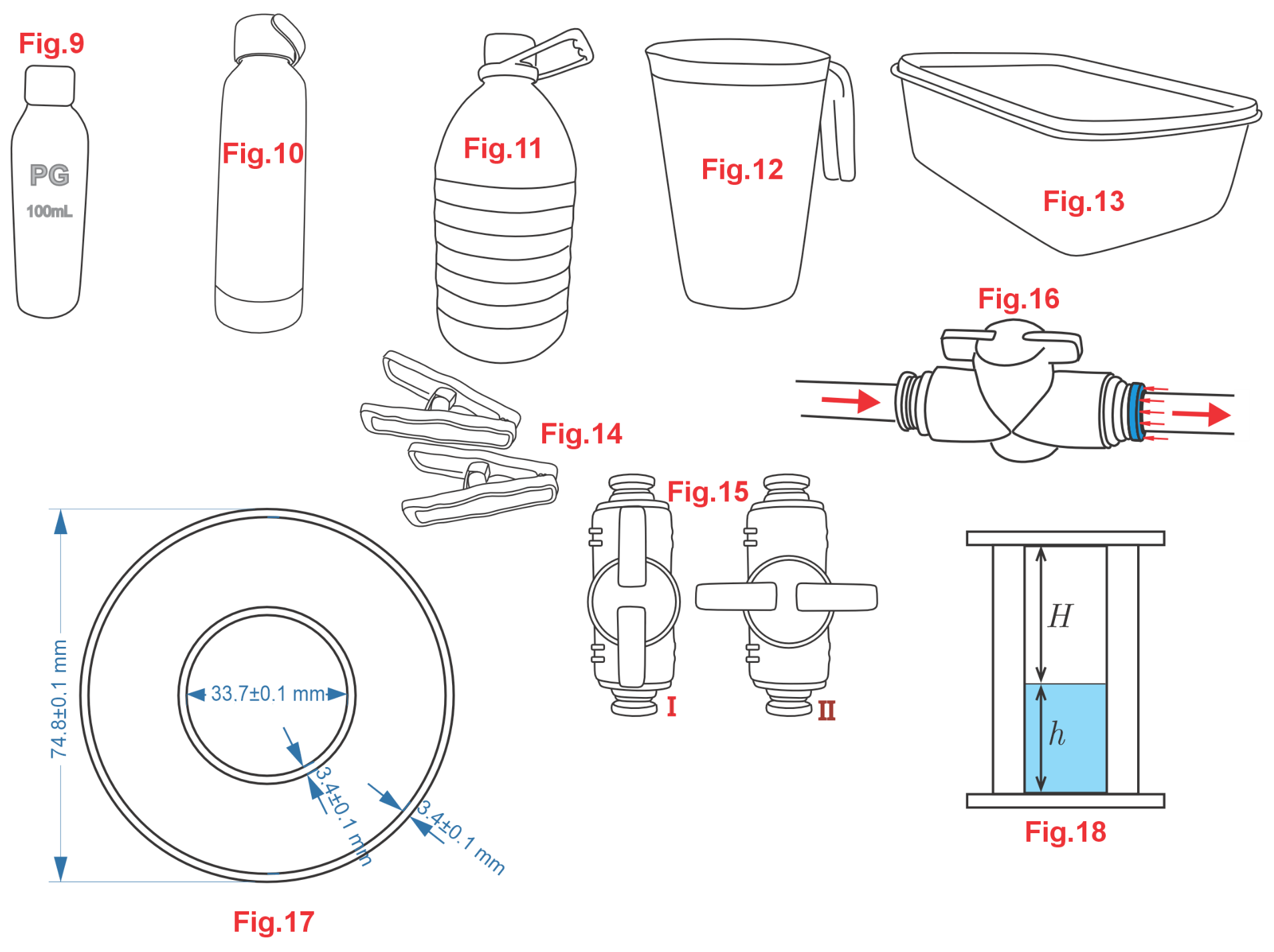
The following materials are supplied for the experiment.
- Two 100 mL syringes with a connecting hose (Fig.7). One syringe is for water, the other for PG.
- Propylene glycol (PG): A container with 100 mL of PG, whose vapor pressure is negligible over the temperature range used in this experiment (Fig.9). Warning: PG is miscible with water. It can also hydrate if open to the air. It is recommended that you keep the container closed while not using it.
- Cold water: A thermal container with 500 mL of cold water (Fig.10).
- Room-temperature water: A bottle of water at room temperature (Fig.11).
- Pouring container: A container used for pouring water (Fig.12).
- Excess-water jug: A jug for collecting excess water (Fig.13).
- Clips: For securing hoses and supporting components during the experiment (Fig.14).
- Paper towels for cleanup.
Important Operating Notes
Keep the following notes in mind when setting up and operating the apparatus:
- Valve positions: Each valve has only two positions: open (I) and closed (II) (Fig.15).
- Hose connection: To remove a hose, push the hoop and pull the hose out. To insert a hose, push it fully into place (Fig.16). Note that the apparatus is fully assembled at the start of the exam and the hoses normally do not need to be reconnected in the usual operation of the apparatus.
- Cylinder dimensions: Figure 17 shows the cross-sectional dimensions of the cylinders.
- Notation: Figure 18 defines the notation used for the IC contents: is the height of the liquid, and is the height of the air above the liquid.
- Volume corrections: The internal volume of the connecting hoses is approximately compensated by the volume of the temperature sensor inside the IC. Therefore, these effects should be neglected.
Constants and Reference Values
The following constants and reference values are used throughout the experiment:
- Avogadro constant:
- Specific heat capacity of water:
- Density of water:
- Molar mass of water:
- Molar mass of air:
- Molar volume of an ideal gas at normal conditions: , for and
Part A. Isochoric (isovolumetric) process of an ideal gas (4 т.)
CA obeys the ideal gas equation of state,
where is the universal gas constant.
Procedure
Introduce PG into IC to cm and close valves D and E. This ensures that the volume of CA is fixed.
The density of ambient air in Bucaramanga varies with local temperature and pressure. For the following question, use the time-averaged value .
A1. Determine the mass , number of moles , and the total number of air molecules of the CA. [0,4 т.]
- Fill OC with room temperature water close to the top.
- Turn on the heater. Don’t forget to homogenize the temperature by using the pump.
A2. Record in a table the pressure of the CA as a function of its temperature . [1 т.]
A3. From the data obtained in question A2, plot the behavior of pressure as a function of temperature. [0,9 т.]
Under IPhO competitive conditions, the sensors may be intentionally decalibrated to alter the expected value of with respect to the reference value.
A4. Use the graph from A.3 to determine the experimental value of . [1 т.]
The thermal pressure coefficient at constant volume is defined by the relationship:
where is the pressure of the system at the reference temperature as indicated in the reference constants and values.
A5. Determine the value of the coefficient for air. [0,7 т.]
Remove the PG from the IC and clean it before proceeding to the other parts. If you proceed to part B, do not remove the hot water from OC.
Part B. Vapor Pressure (8 т.)
In a closed container containing a liquid and its vapor at equilibrium, the vapor pressure depends on the absolute temperature according to the Clausius–Clapeyron equation:
Here, is the reference temperature, taken as 0 °C. is the vapor pressure at . is the universal gas constant, and is the molar latent heat of vaporization of water.
Procedure
Remember that PG and water are miscible. Use different syringes for water and PG
- Fill the OC with water until the water level is close to the top.
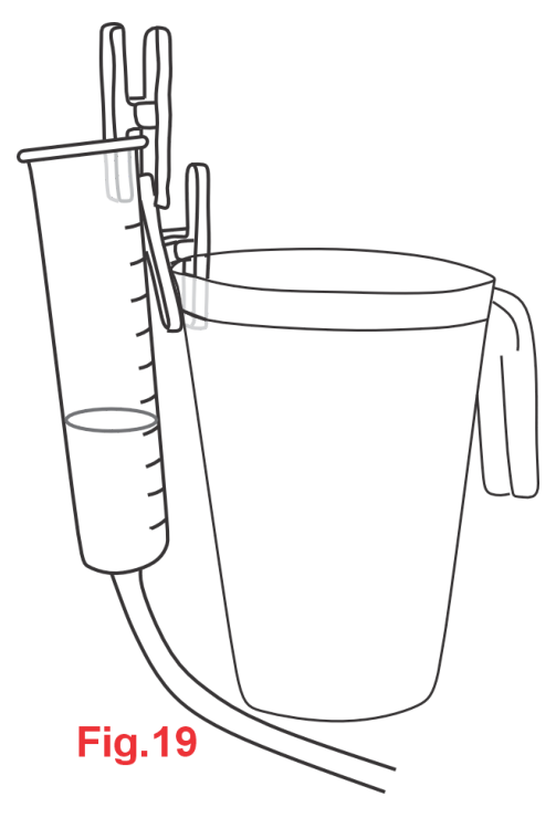
- Fill a syringe with water, connect it to IC and open valve E, remove the syringe plunger, and raise the syringe until it reaches the water level at cm. Close valve E and then secure the syringe to the jug as shown in Figure 19. This arrangement keeps the pressure inside the IC approximately equal to the atmospheric pressure. Make sure no air bubbles remain in the hose.
- Heat the water in the OC to 65 °C. Remember to use the recirculator system to homogenize the water temperature.
- Wait until the temperature starts to decrease to start recording as a function of .
- To lower the temperature further, you may replace the water in the OC with the supplied cold water at the appropriate time.
B1. Record the height as a function of temperature in a table [1 т.]
B2. Use the data obtained in B1 to plot as a function of . [1 т.]
The vapor pressure is relatively small around room temperature and the curve may be approximated as linear.
B3. Use the graph from question B2 to extrapolate and find the value of ( at 0 °C). [0,5 т.]
B4. Assuming that IC contains both dry air plus water vapor, deduce an algebraic expression for the vapor pressure in terms of (atmospheric pressure), , , and .
For the purposes of this problem, you can assume that the vapor pressure at 0 °C is zero. [1 т.]
For the following questions, use the reference value .
B5. Using equation (3) and the expression from question B4, construct an appropriate graph to determine the experimental value of . [4 т.]
B6. From the value of , determine , (the latent heat of vaporization per unit mass) indicating the formula that you used. [0,5 т.]
Part C. Heat Conduction (8 т.)
In this part of the exam, you will study the heat exchange between the water in the OC and the water in the IC through the wall that separates them. By analyzing the time evolution of the water temperature in the IC, , and the water temperature in the OC, , the objective of this section is to estimate the effective thermal resistance of the wall, the equilibrium temperature of the system, and the thermal conductivity of acrylic.
Heat conduction through a solid wall follows the relation:
where is the heat received by the water in the IC through the wall during the time interval . The effective thermal resistance depends on the material and geometry of the wall separating IC and OC.
Procedure
- Set the water level in the OC to cm.
- Heat the water in the OC to 65 °C. Use the pump to homogenize the water temperature.
- Set the water level in the IC to cm and start the stopwatch.
C1. Record the internal temperature and external temperature as a function of time [1 т.]
C2. On a single graph, plot and as functions of time . [1 т.]
For questions C3 and C4, ignore the heat capacity of the apparatus. refers to the equilibrium temperature that would be reached by both IC and OC if there were no heat transfer to the environment.
C3. Plot as functions of both and on the same graph with and together on the same temperature axis and on the other axis. [0,7 т.]
C4. From the graphs constructed in C3, determine . It is not necessary to calculate uncertainty for this question. [1,1 т.]
If the variables are measured a finite number of times, Equation (4) can be expressed as
where represents the measurement number and are the average temperatures at each cylinder during the interval to
C5. Graph the expression on the left hand side of Equation 5 as a function of the expression on the right hand side [1 т.]
C6. Determine the value of from the graph constructed in C5. [1,6 т.]
Fourier’s law for radial heat conduction through a slim cylindrical wall can be written as:
where is the area of the wall, is the thermal conductivity of the wall material, and denotes the distance from the axis of the cylinder.
C7. Using equations (4) and (6), determine the value of the thermal conductivity of acrylic (the material separating IC and OC), indicating the formula that you used. [1,6 т.]
Решение
The archived official solution uses a different order for A1–A3 and different marks for several subtasks. Its printed labels and marks are retained below: solution A1 corresponds to question A2; solution A2 to question A3; solution A3 to question A1. Other source discrepancies are listed in the source note.
Part A. Isochoric process (4 т.)
A1. Record the pressure as a function of the temperature .
| T (K) | P (kPa) |
|---|---|
| 303 | 96.4 |
| 305 | 96.9 |
| 307 | 97.4 |
| 309 | 98.2 |
| 311 | 98.8 |
| 313 | 99.3 |
| 315 | 100.5 |
| 317 | 101.3 |
| 319 | 102.2 |
| 321 | 102.5 |
| 323 | 102.8 |
| 325 | 103.9 |
| 327 | 104.1 |
| 329 | 104.5 |
| 331 | 105.0 |
| 333 | 105.9 |
[0,5 т.]
A2. From the data obtained in A1, plot the behavior of pressure as a function of temperature.
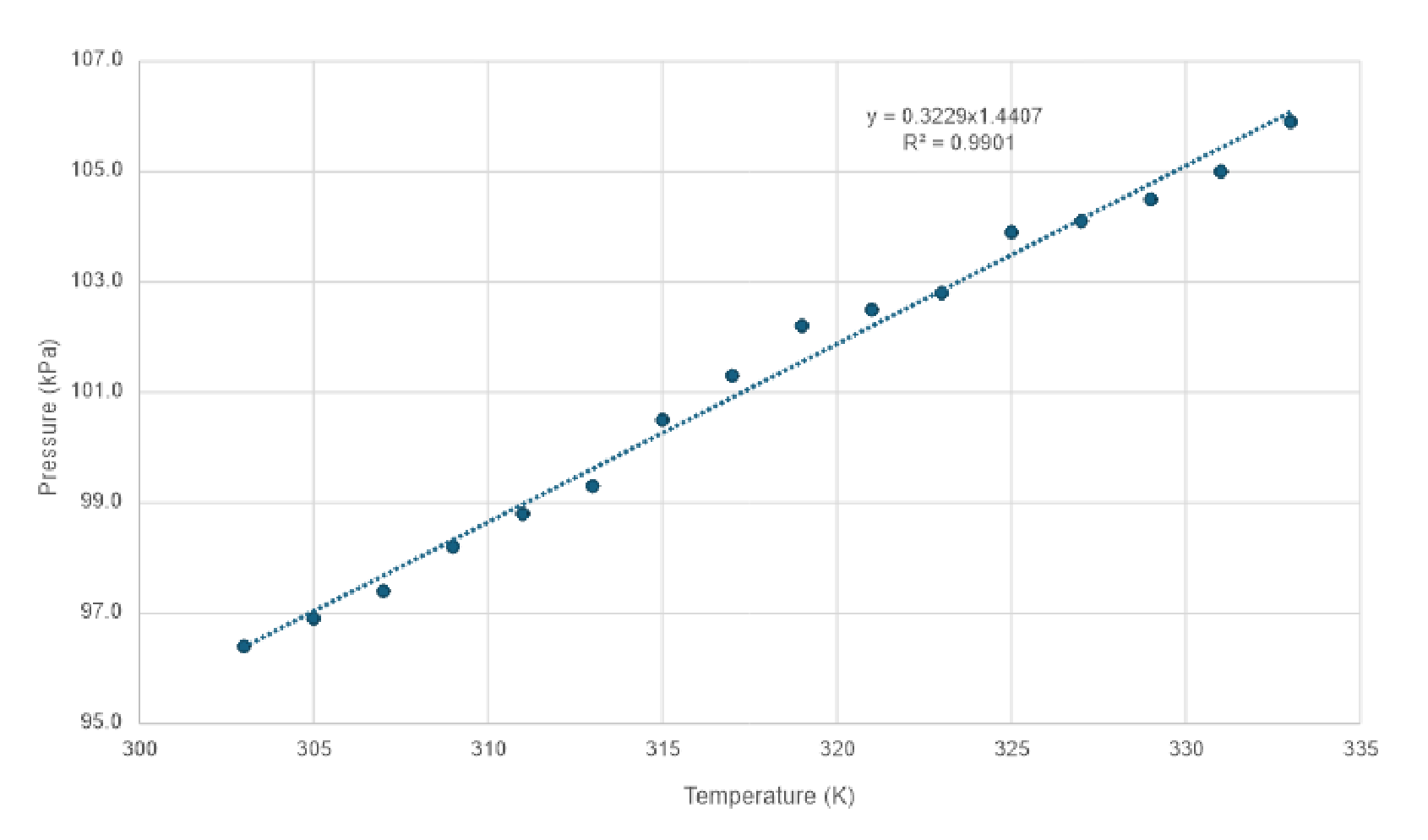
[0,9 т.]
A3. Determine the mass , number of moles , and total number of air molecules of the CA.
For cm; mL; g
; mmol.
. [0,9 т.]
A4. Use a graph to determine the experimental value of the universal gas constant .
Constant . [1 т.]
A5. Determine the value of the thermal coefficient of expansion at constant volume.
theory [0,7 т.]
Part B. Water vapor pressure. Latent heat. (8 т.)
B1. Record the data relating the temperature with the height .
| H (cm) | T (K) | Pv (kPa) |
|---|---|---|
| 9.1 | 339 | 18.6 |
| 8.9 | 338 | 17.1 |
| 8.8 | 337 | 16.4 |
| 8.6 | 336 | 14.8 |
| 8.5 | 335 | 14.1 |
| 8.3 | 334 | 12.4 |
| 8.2 | 332 | 11.9 |
| 8.0 | 329 | 10.6 |
| 7.8 | 326 | 9.2 |
| 7.7 | 324 | 8.7 |
| 7.6 | 323 | 7.8 |
| 7.5 | 320 | 7.4 |
| 7.2 | 315 | 5.2 |
| 7.1 | 313 | 4.5 |
| 7.0 | 312 | 3.5 |
| 6.9 | 309 | 3.1 |
| 6.8 | 304 | 3.3 |
| 6.6 | 299 | 2.0 |
| 6.5 | 293 | 2.5 |
| 6.4 | 290 | 2.0 |
[0,5 т.]
B2. Plot as a function of .
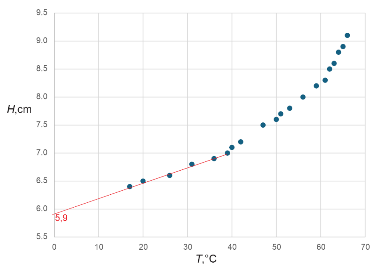
[1 т.]
B3. Use the graph from B2 to extrapolate the value of at 0 °C.
The extrapolation in the graph gives us that cm, at this height corresponds ml for °C. [0,5 т.]
B4. Assuming that air behaves like an ideal gas and taking °C, deduce an expression for vapor pressure in terms of , , , , and .
[1,5 т.]
B5. Using equation (3), construct an appropriate graph to determine the molar latent heat of vaporization of water . Find the value of .
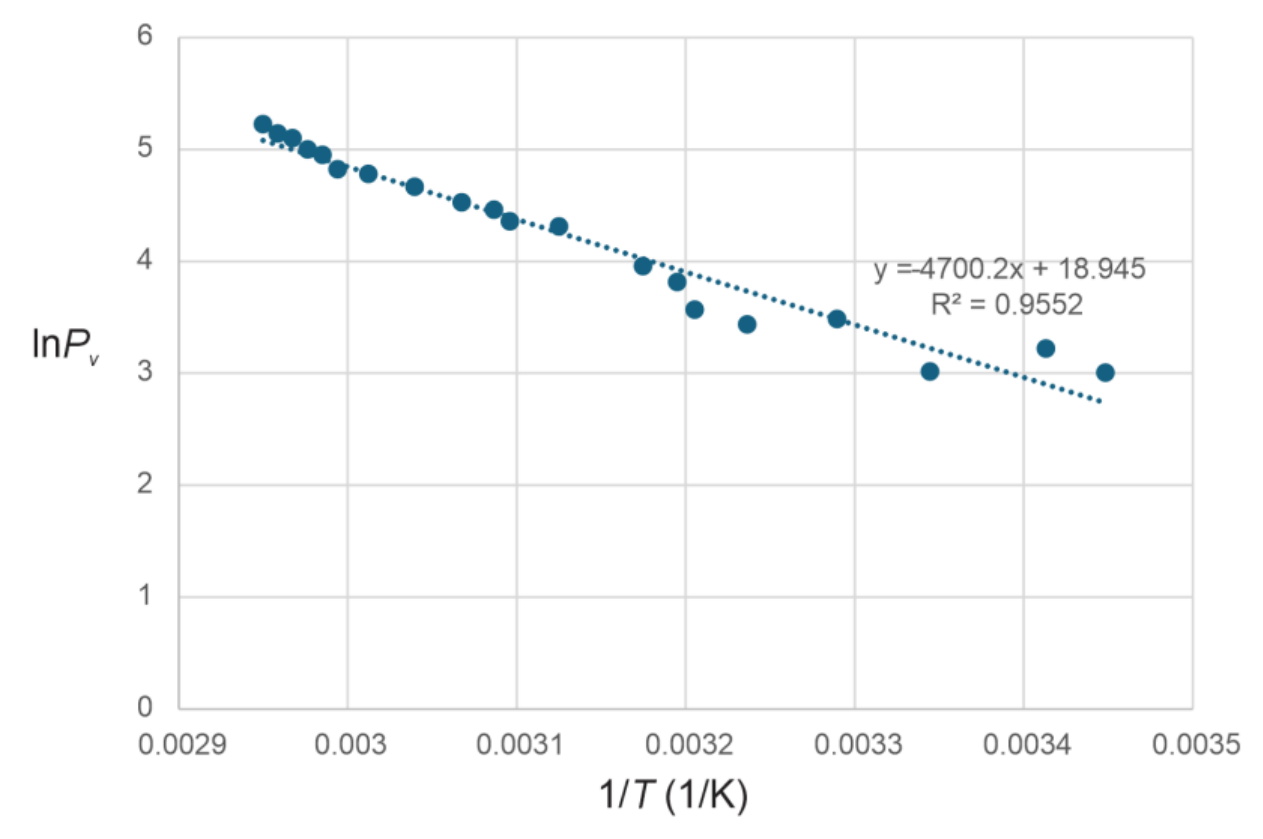
The slope K.
The value of kJ/mol. [4 т.]
B6. From the value of , determine , indicating the formula that you used. Show your uncertainty calculation explicitly
The specific heat of vaporization is kJ/kg. [0,5 т.]
Part C. Heat conduction (8 т.)
C1. Record the values of time , internal temperature , and external temperature .
| t (s) | Tue (°C) | Te (°C) |
|---|---|---|
| 0 | 30.4 | 66.6 |
| 60 | 34.9 | 64.5 |
| 120 | 38.4 | 62.2 |
| 180 | 41.0 | 60.8 |
| 240 | 43.1 | 59.3 |
| 300 | 44.7 | 58.1 |
| 360 | 46.1 | 57.0 |
| 420 | 47.2 | 56.0 |
| 480 | 48.0 | 55.1 |
| 540 | 48.6 | 54.3 |
| 600 | 49.1 | 53.5 |
| 660 | 49.4 | 52.8 |
| 720 | 49.7 | 52.2 |
| 780 | 49.8 | 51.6 |
| 840 | 49.9 | 51.0 |
[0,5 т.]
C2. On a single graph, plot and as functions of time .
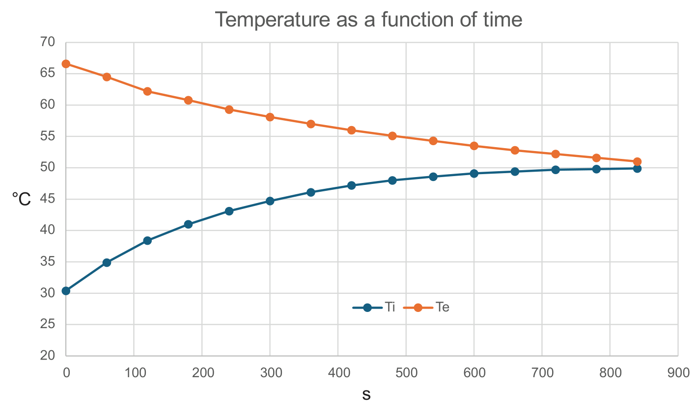
[1 т.]
C3. On the same set of axes, plot as a function of and as a function of .
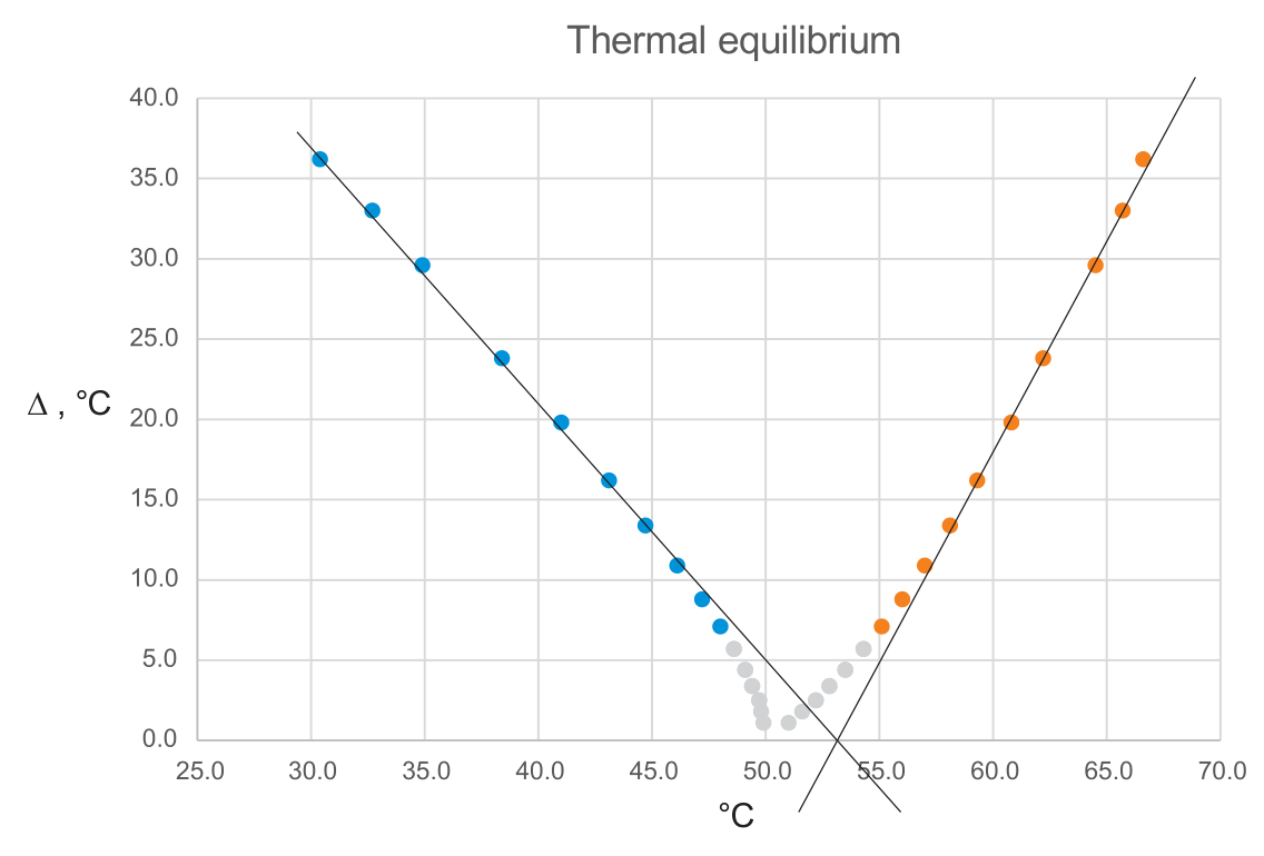
[1 т.]
C4. From the graphs constructed in C3, determine . It is not necessary to calculate uncertainty for this question.
By extrapolation °C. [0,8 т.]
C5. Construct the graph indicated by expression (5).
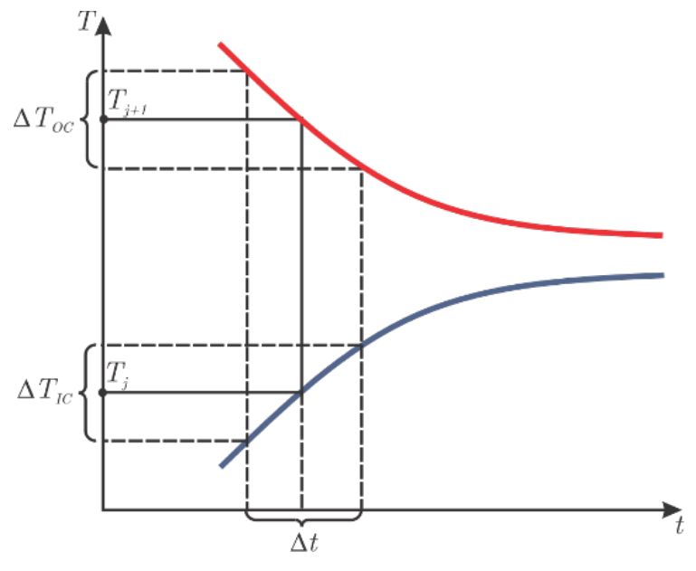
Here represents the measurement number, is the variation in the temperature of the water contained in IC during the time interval between two consecutive measurements and is the variation in the temperature of the hot water in OC and in the IC in the same time interval. [1,5 т.]
C6. Express the value of the effective thermal conductance of the wall and determine the value of from the graph constructed in C5.
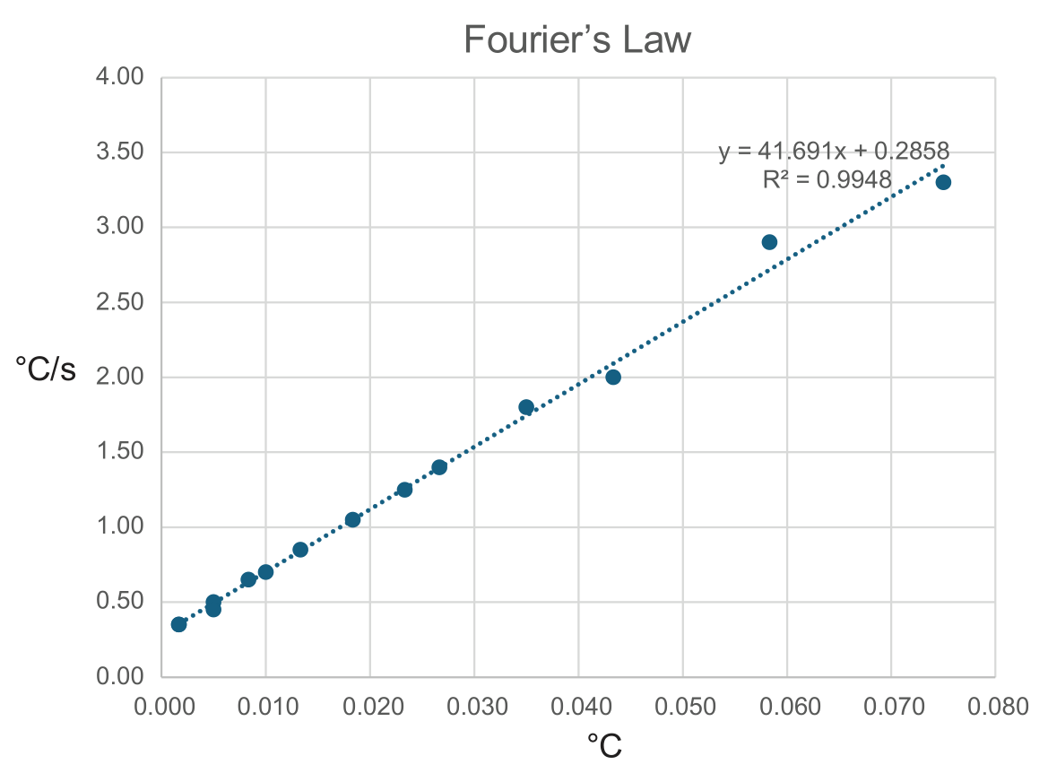
The slope turns out to be . This is the same thermal conductance of the wall.
The body of water g.
Thermal Resistance . [1,6 т.]
C7. Using equations (4) and (6), determine the value of the thermal conductivity of acrylic, indicating the formula that you used. Show your uncertainty calculation explicitly.
Is valid ( uncertainty is dominant)
Or
Not integrated
[1,6 т.]
Оригинал в Архива: exp.pdf · официални решения: exp_sol.pdf