ISPhO 2024, Теория — Задача 2. Memristors and NVRAM
ISPhO, July, 2024 — T2. Memristors and NVRAM
Условие
Introduction. Non-volatile random access memory
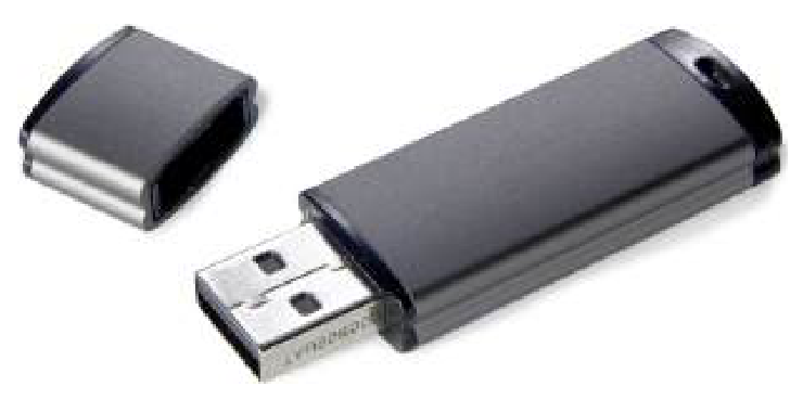
NVRAM (Non-Volatile Random Access Memory) is a type of random access memory capable of storing information in the absence of electrical power. The ability to independently access information in any memory cell at any time and to store data without constant power supply opened huge technological capabilities at the time of its invention, and we still use it today (Fig. 1).
There are several types of NVRAM. The most popular of them are based on semiconductor elements, and therefore are difficult to consider. In this task, we will examine both a promising realization of NVRAM – ReRAM (Resistive Random Access Memory) based on memristors, and a realization that have already almost disappeared into the past – ferroelectric memory (FeRAM, Ferroelectric Random Access Memory) based on segnetoelectrics.
Part A. Memristor
In 1971, Prof. Leon O. Chua published a theoretical justification for the possibility of a memristor – an electrical element in which the relationship between voltage and current depends on the total charge flowing through the element.
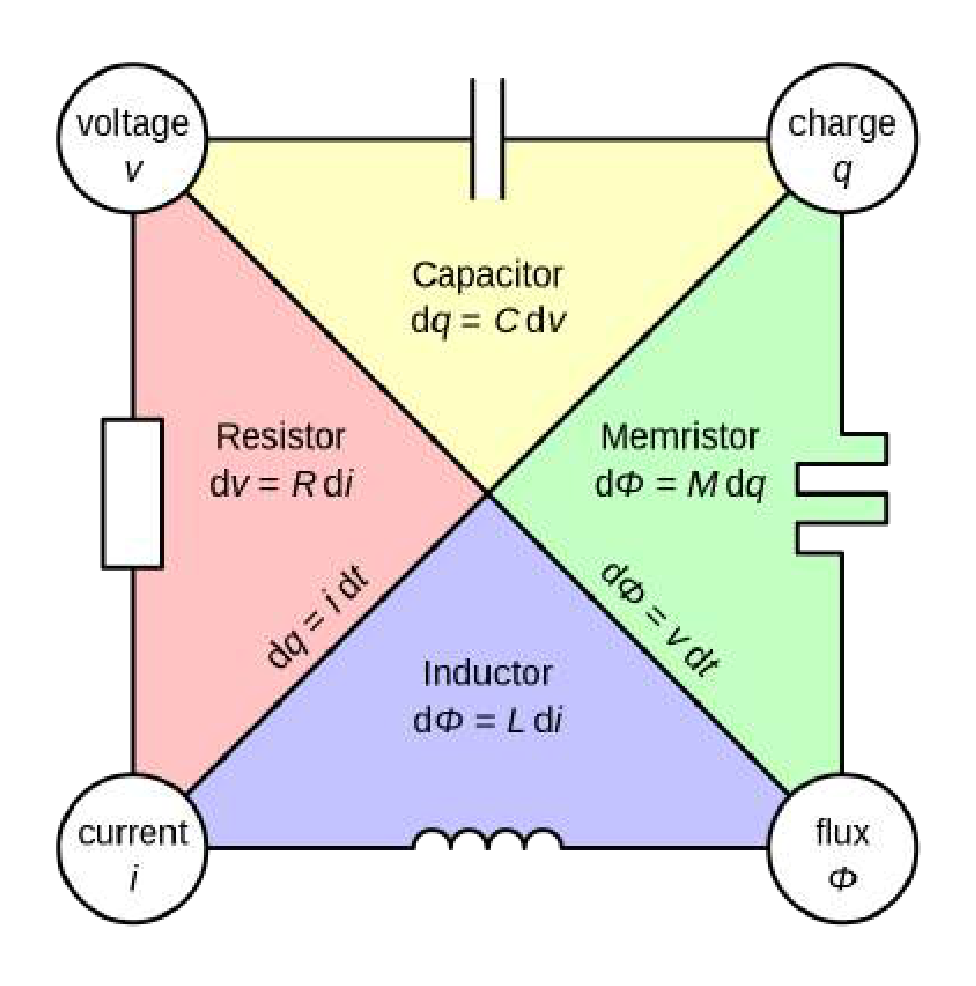
Memristor-based computing systems are currently attracting serious attention of researchers in the field of artificial intelligence, as they work on principles similar to the neurons of the human brain and can potentially achieve the same results with much lower energy consumption and relative architecture simplicity.
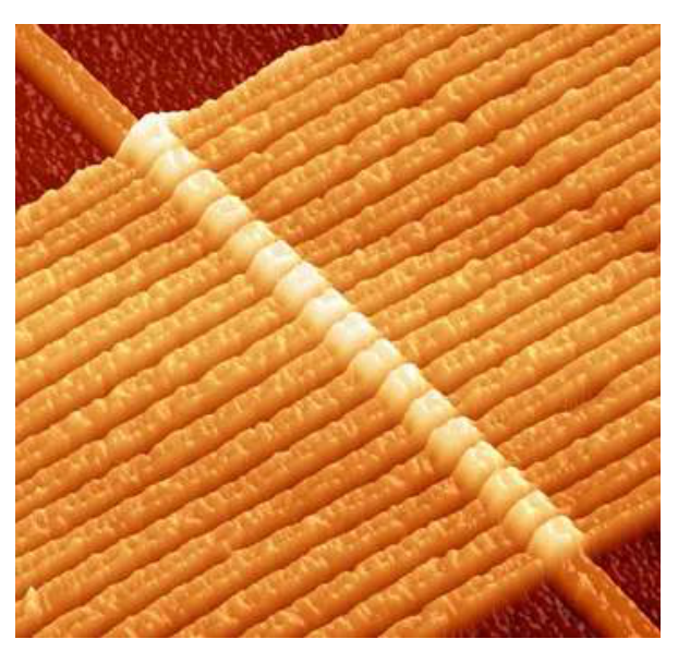
For a long time, the memristor existed only ”on paper”, until in 2008 Hewlett-Packard presented the first working prototype of a memristor. In this prototype, the change in resistance depending on the flowing charge was achieved due to electrochemical reactions occurring in the contact area of two different materials (Fig. 3).
Since electrochemical reactions are reversible, the resistance of this prototype memristor tends towards its equilibrium value in the absence of current. For the simplest theoretical description of such a memristor, we can use the Williams–Strukov equations:
Here is some parameter determined by the internal state of the system, are known quantities, is current through the memristor, and () are the resistances of the memristor in the ”off” and ”on” states, respectively.
Let’s first consider the evolution of the memristor state under a constant voltage . Initially, the memristor is ”off” (i.e. ).
A1 Obtain a differential equation on . Express your answer in terms of , , , , and .
For convenience, let’s introduce . We will assume that the memristor is on if the value of its internal parameter differs from the equilibrium one by no more than 10%. For simplicity in all the remaining points of this part, work in the limit of large voltages .
A2 Simplifying the equation from A1 in this limit, find the minimum value of at which the memristor can be considered to be on. Express your answer in terms of , , , and .
A3 Find the time required to switch the memristor from the initial off state to the on state. Express the answer in terms of .
A4 Find the minimal energy requires to switch the memristor from the initial off state to the on state. Express your answer in terms of , , , and .
Part B. Memristor hysteresis
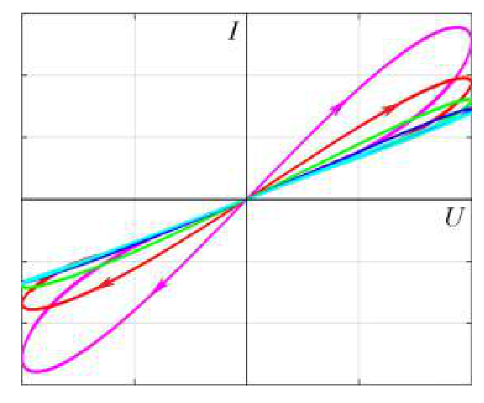
If an an oscillating voltage is applied to the memristor, its resistance will also oscillate due to fluctuations in current and charge flowing through it. Because of this, at the same voltage, the current through the memristor will depend on whether the voltage increases or decreases. In coordinates, this behavior will look like hysteresis loops (Figure 4). It turns out that by measuring the characteristics of these loops it is possible to calculate some important parameters of the memristor, which we will do in this part.
Suppose an oscillating voltage is applied to the memristor, and .
B1 Find in the first-order approximation by . From here, find (also to a first-order approximation), – the absolute difference in currents on different branches of the hysteresis loop at the same voltage . Express your answers in terms of , , , , , and .
Let’s introduce the hysteresis loop width as:
where is the amplitude of the current oscillations.
B2 Express in terms of , , , and .
Since the hysteresis curve width is easy to measure, it can be used to determine the parameters of the memristor. The table below shows the dependence of on the frequency of the voltage applied to the memristor at voltage .
| 100 | 250 | 500 | |
|---|---|---|---|
| 47.8 | 54.1 | 36.7 |
Also, the resistance of the memristor was measured in the off state.
B3 From this data, calculate and with three significant figures.
Part C. ReRAM energy efficiency
The information is written to the prototype memristor element under a voltage of .
C1 Calculate with two significant figures the time in which the write takes place.
C2 Calculate with two significant figures the minimum amount of energy required to write one bit of information.
As you can see, the researchers at HP are still pretty far from perfect...
Part D. Segnetoelectrics and FeRAM
In most materials, polarization is identically equal to zero in the absence of an external field. However, there is a class of materials called segnetoelectrics that remain polarized even when no field is applied. The ability to store information in the direction of polarization and to read and rewrite it easily was the basis for the creation of ferroelectric memory (FeRAM). In this part of the task we will investigate these properties of segnetoelectrics in detail.
The volume energy density in a segnetoelectric depends on the polarization and the external electric field as:
where are material-specific quantities. The equilibrium values of polarization are determined by local minima of . In the absence of an external field, there are two equilibrium states of a segnetoelectric with the same energy, transitions between which are impossible, which is used for information storage.
Consider a segnetoelectric material that is initially in the state with negative , and at some moment the external electric field is switched on and starts to increase. Then, when the field reaches some critical value , the local minimum with smaller polarization disappears and the system jumps to the only remaining equilibrium state, dissipating at this moment the energy per unit volume in the form of heat. If the external field is then slowly turned off, the system will move to an equilibrium state with positive (that is, its state will change). This is used to record information.
D1 Find at what critical field one of the equilibrium states of the segnetoelectric in the above situation disappears. What is the polarization in this state just before the ”disappearance”? Express your answers in terms of and .
Hint: consider the second derivative of energy density at the moment of ”disappearance”.
D2 What polarization will the segnetoelectric have right after the ”jump”? Express your answer in terms of and .
D3 Find the dissipated energy per unit volume. Express your answer in terms of and .
The first commercial FeRAM samples used lead zirconate titanate, for which and . The memory cells were fabricated on a process, which can be used to estimate the cell volume.
D4 What amount of energy is required to write bits of data to FeRAM? Express your answer in terms of , , and . Calculate this quantity with two significant figures.
Отговори
- A1
- A2
- A3
- A4
- B1
- B2
- B3
- C1 0.00072 s
- C2 0.0001 J
- D1
- D2
- D3
- D4
Решение
A1. By plugging in into the second Williams–Strukov equation, we obtain:
A2. The stationary value of can be found by solving the equation
From this one can see that in the limit of large the stationary value of will also be large, so we can neglect 1 in the denominator. From this we get:
A3. In the limits of large the equation from A1 can be rewritten in the form:
A4. Minimal energy is equal to Joule heat dissipation during the off-to-on switch:
B1. As the term with current in the second Williams–Strukov equation is already the next order by the aforementioned quantity, we can plug in the zeroth-order approximation for current which is simply , so that:
Substituting , we obtain:
The difference between actual current and zeroth-order value can be calculated as:
Then:
B2. Because , and in the zeroth order
B3. The dependency of vs is linear with a slope of and intercept . We can find the answers using the least squares method:
| 100 | 47.8 | 628 | 0.395 | 6.57 |
| 250 | 54.1 | 1571 | 2.467 | 14.52 |
| 500 | 36.7 | 3142 | 9.870 | 42.80 |
C1. Using the result of A3, we obtain:
C2. Using the result of A4, we obtain:
D1. Equilibrium states can be found by solving the equation:
As we pass the critical field, one of equilibrium states disappears, which means that the derivative no longer crosses zero at this point. This means that at the critical field this derivative only touches zero, so at this point:
And we conclude that one of equilibrium states disappears at the point (don’t forget that we take ):
D2. We basically need to find a root of a cubic equation
when we know its root of multiplicity 2. Simlply dividing by , we get:
D3. Plugging in expressions obtained in the previous tasks:
D4. To write one bit of data we generally need energy of the order:
Then, to write the whole 1 TiB, we would need:
Оригинал в Архива: T2.pdf · официални решения: T2_sol.pdf