IZhO 2026 — Задача 2. Steam Engine
Автор: Olympiads XYZ · транскрипция на официалните материали
Проверена срещу оригинала на 13.9.2026 от същия модел, който я е транскрибирал (без независима проверка)
XXII International Zhautykov Olympiad/Theoretical Competition · 11 януари 2026 г. · 10 т.
Внимание: Бележка към темата
Solutions not yet attached (not in window).
Условие
In this problem, we consider a simplified theoretical model of one type of steam engine. Note that at present such an engine is used only as a technical toy.
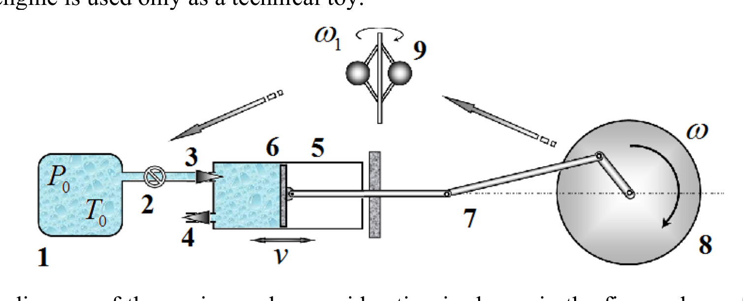
A schematic diagram of the engine under consideration is shown in the figure above. There is a steam generator 1 (a boiler with water and a heater, as well as a system for additional superheating of the steam). The generator may be regarded as a large vessel containing water vapor (without air), in which the pressure and temperature are maintained constant. The heated steam is supplied through a pipe to the working cylinder 5 with a movable piston 6. The pipe is equipped with a steam supply regulator 2 controlled by a Watt centrifugal governor 9. The working cylinder has two valves: an inlet valve 3 and an outlet valve 4. These valves open and close at certain positions of the piston. The movable piston is connected to a system of rods 7 that converts the translational motion of the piston into rotational motion of a massive flywheel 8 mounted on the engine shaft. By means of a belt drive, this wheel is connected to the Watt governor, whose angular velocity is equal to the angular velocity of the flywheel. The amount of steam passing through the steam supply regulator 2 depends on the rotational frequency of the governor. The flywheel shaft is connected to the working device (for whose sake all engines are created).
In all parts of the problem, steady operating regimes are considered, in which the angular velocities of rotation of the shaft and the Watt governor remain constant. Of course, the transition to such regimes is possible only in the presence of friction; however, in calculations of the steady motion, friction may be neglected.
Assume that the adiabatic index of water is , the molar mass of water is .
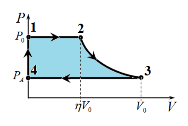
Part 1. Steam Engine without a Governor The ideal cycle of the engine under consideration in the limit of infinitely slow motion is shown on the diagram. Here is the volume of the part of the cylinder between the cylinder end face and the piston that is occupied by steam (hereafter referred to as the working volume); is the maximum working volume; and is the pressure of the steam in this volume.
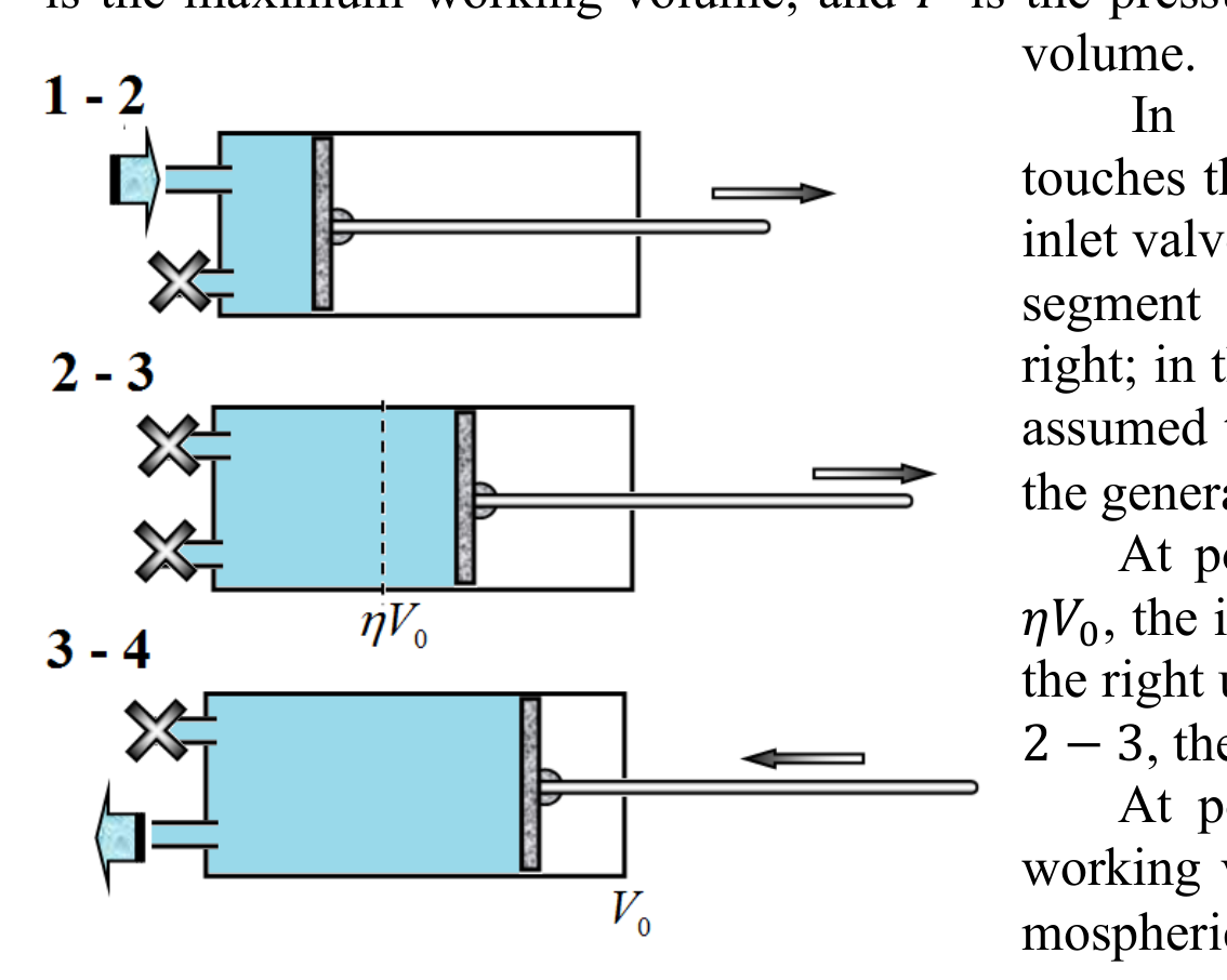
In state 1, the piston touches the cylinder wall and the working volume is zero. The inlet valve opens, and steam begins to enter the cylinder. Along segment 1–2 of the cycle, the piston moves slowly to the right; in this process, the steam pressure in the cylinder may be assumed to be equal at all times to the pressure of the steam in the generator, .
At point 2, when the working volume reaches the value , the inlet valve closes, and the piston continues to move to the right under the action of the steam pressure. Along segment 2–3, the expansion process is adiabatic.
At point 3, the piston reaches its extreme position, the working volume is maximal, and the pressure drops to the atmospheric value . After that, the outlet valve opens, and the piston expels the steam into the atmosphere.
When the piston returns to the extreme left position, the outlet valve closes and the inlet valve opens again (segment 4–1).
2.1 Determine the value of the coefficient .
2.2 To prevent steam condensation, its minimum temperature must be higher than the condensation temperature at atmospheric pressure, .
Determine the required value of the steam temperature (in degrees Celsius) such that during the expansion process the temperature does not drop below the condensation temperature .
In what follows, assume that in the considered model the parameters and are equal to the values found above.
2.3 Calculate the mass of steam entering the cylinder during one cycle.
2.4 Calculate the work performed by the engine during one cycle.
2.5 Next, consider the operation of the engine in a real regime, taking into account that the piston moves with some finite velocity. Assume that the flywheel rotates with a constant angular velocity . Strictly speaking, in this case the motion of the piston is not uniform. However, as an approximation, the piston velocity in one direction may be taken to be constant and equal to its average velocity. In this problem, it is convenient to consider the rate of change of the working volume, .
Express the average rate of change of the working volume of the cylinder in terms of the maximum working volume and the angular velocity of the flywheel.
2.6 During the piston motion, the steam pressure in the cylinder during stage 1–2 of the cycle differs from the steam pressure in the generator . Assume that the rate of steam inflow is proportional to the pressure difference across the steam regulator 2, i.e. where is a constant coefficient determined by regulator 2. In this part, take it to be constant and equal to . Assume that the steam expansion process at all stages of the cycle is adiabatic.
Derive a differential equation describing the change in the mass of gas in the cylinder while the inlet valve is open. Besides the unknown function , this equation should contain only known quantities.
2.7 Show that at a constant piston velocity the steam pressure in the cylinder remains constant.
2.8 Obtain an algebraic equation for determining the steam pressure in the cylinder during stage 1–2 of the cycle.
To approximately solve the resulting equation (i.e., to find the pressure ), make the following mathematical approximation: assume (only in this part of the problem) that the adiabatic index of water vapor is . In addition, when calculating the work performed by the steam, neglect atmospheric pressure.
2.9 Using the above approximation, express the steam pressure in the cylinder during stage 1–2 in terms of the pressure and the other known parameters of the problem.
2.10 Calculate the numerical value of the pressure at an angular velocity of the shaft .
2.11 Show that the formula for calculating the work performed by the engine during one cycle when the flywheel rotates with a constant angular velocity can be written in the form . Calculate the numerical values of the parameters and in this formula.
2.12 Assume that, in addition to the torque exerted by the piston, a constant torque from the working device acts on the engine shaft.
Express the average steady-state angular velocity of the wheel in terms of the torque , the coefficient , and the parameters and .
2.13 Calculate the maximum torque at which the engine can operate.
2.14 Sketch a schematic graph of the dependence of the angular velocity of rotation on the torque .
Part 2. Governor without the Engine The angular velocity of rotation of the engine flywheel depends on the torque transmitted to the working device. When this torque decreases, the angular velocity may increase sharply, which can lead to engine failure and its further destruction. To avoid such situations, various automatic control systems are used, one of which is the Watt centrifugal governor.
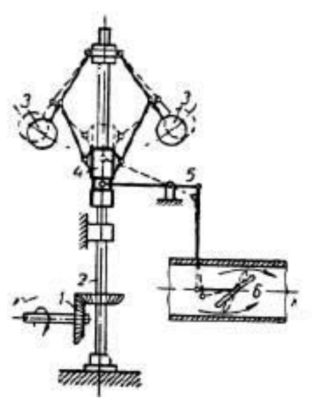
The principle of its operation is quite simple. The rotation of the engine shaft is transmitted through a drive to the shaft of the governor. During the rotation of the governor shaft, the balls deviate from the axis under the action of the centrifugal force; the faster the shaft rotates, the farther apart the balls move. The levers interact with a sleeve and move it along the shaft axis. Through a system of levers, the displacement of the sleeve is transmitted to the steam supply throttle in such a way that when the rotational speed of the shaft increases, the steam supply decreases, and when it decreases, the steam supply increases.
For solving this problem, the technical details of the specific device are not essential. Let us consider an idealized schematic model of the governor. A hinged rhombic frame is mounted on a vertical shaft rotating with a constant angular velocity . The upper vertex of the frame is fixed, while the lower vertex can freely slide along the shaft. Two massive balls are attached at the lateral vertices of the frame. It may be assumed that in the absence of shaft rotation . When the shaft rotates, the balls rise, deviating by an angle from the vertical. This leads to a reduction in the steam supply to the working cylinder. We assume that the coefficient , which characterizes the steam flow rate, is related to the deflection angle by the simple relation where is the coefficient defined earlier.
The length of a side of the frame is .
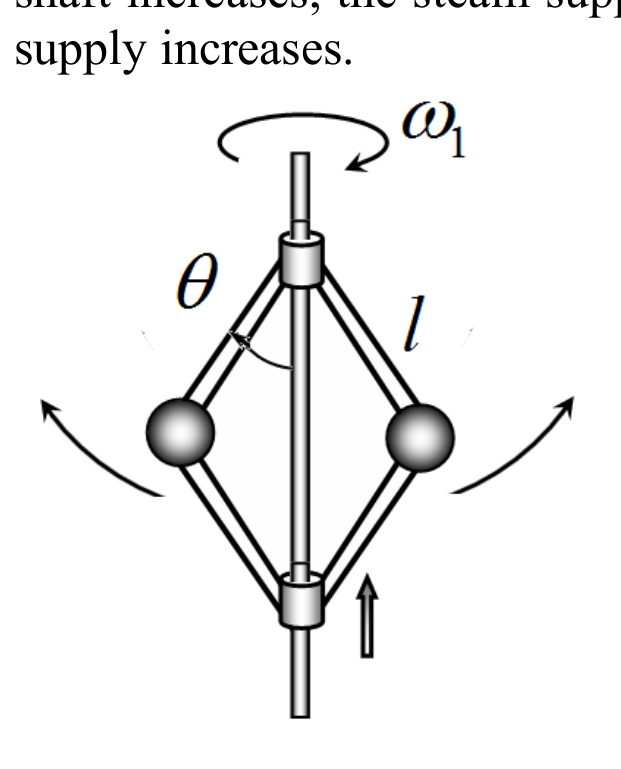
2.15 Find the dependence of the deflection angle of the balls from the vertical on the constant angular velocity of the governor.
2.16 Sketch a schematic graph of the dependence of the coefficient on the angular velocity of the governor.
2.17 Part 3. Engine with a Governor
Find the dependence of the steady-state angular velocity of rotation of the engine shaft on the torque for the governor system described above.
2.18 Sketch a schematic graph of the resulting dependence.
Решение
Покажи официалното решение
Оригинал в Архива: IZhO-2026-Theory_eng.pdf · официални решения: IZhO-2026-Theory_eng_sol.pdf