NBPhO 2025, Теория и експеримент — Задача 4. Black Box
Nordic-Baltic Physics Olympiad 2025 · 12 т.
Условие
— Eero Uustalu. Tools: a black box with a yellow and a blue lead, two multimeters, a voltage source (that is connected in series with a resistor to limit the maximal current), wires, sheets of graph paper. In the black box, there are three diodes and a resistor.
You are allowed to connect your circuit to the power source only through the yellow lead with a built-in resistor (that is already connected to the power source)!
For each series of measurements, also draw the circuit used!
i) Determine the electrical circuit inside the black box. [4 т.]
ii) Determine the resistance of the resistor. [2 т.]
iii) Determine the opening voltages of all the diodes (at which the current reaches ). [6 т.]
Решение
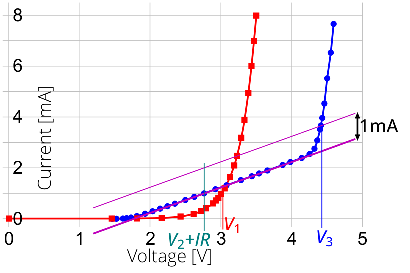
— Eero Uustalu. First we need to assemble a simple circuit allowing us to measure the curve of the black box: voltmeter in parallel to the box, and ammeter in series. The measurement results are shown in the table below, both for forward current (blue) and for reverse current (red) (the headers of the reverse current data has minus sign).
| V (V) | I (mA) | -V (V) | -I (mA) |
|---|---|---|---|
| 4.59 | 7.66 | 3.491 | 7.98 |
| 4.55 | 6.53 | 3.458 | 6.98 |
| 4.50 | 5.52 | 3.423 | 6.00 |
| 4.46 | 4.53 | 3.379 | 4.94 |
| 4.43 | 3.964 | 3.324 | 3.868 |
| 4.41 | 3.665 | 3.279 | 3.178 |
| 4.40 | 3.51 | 3.219 | 2.468 |
| 4.36 | 3.08 | 3.180 | 2.088 |
| 4.32 | 2.756 | 3.121 | 1.637 |
| 4.25 | 2.54 | 3.044 | 1.186 |
| 4.14 | 2.391 | 2.993 | 0.958 |
| 3.98 | 2.23 | 2.956 | 0.817 |
| 3.871 | 2.115 | 2.922 | 0.711 |
| 3.656 | 1.897 | 2.880 | 0.595 |
| 3.539 | 1.781 | 2.784 | 0.403 |
| 3.436 | 1.67 | 2.713 | 0.2931 |
| 3.282 | 1.519 | 2.607 | 0.1847 |
| 3.079 | 1.314 | 2.423 | 0.0801 |
| 2.923 | 1.159 | 2.156 | 0.0219 |
| 2.762 | 0.998 | 1.807 | 0.0037 |
| 2.625 | 0.862 | 1.451 | 0.0006 |
| 2.498 | 0.736 | 0 | 0 |
| 2.351 | 0.593 | ||
| 2.246 | 0.491 | ||
| 2.143 | 0.398 | ||
| 2.036 | 0.2932 | ||
| 1.931 | 0.1989 | ||
| 1.815 | 0.1037 | ||
| 1.732 | 0.0486 | ||
| 1.670 | 0.021 | ||
| 1.617 | 0.0087 | ||
| 1.526 | 0.0016 | ||
| 1.467 | 0.0005 |
These data will be used for all the tasks.
i) (4 т.)
Based on these data, we can determine that there is a single diode allowing negative currents to flow, with no other components in that branch, as the - curve shows the classical exponential dependence characteristic of a diode.
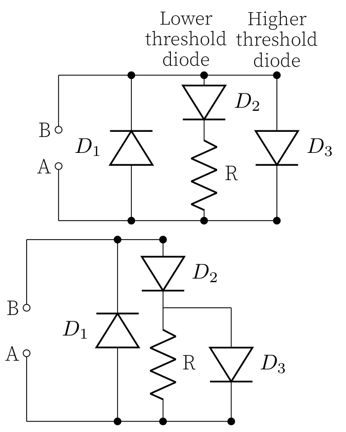
The situation is more complex for positive currents: there must be two parallel branches allowing current to flow. One branch must contain a diode with a lower threshold voltage in series with a resistor, which explains why the initial exponential curve transitions into a linear relationship characteristic of resistive behaviour. The second branch must contain a diode with a higher threshold voltage (approximately ) that only conducts when this voltage is exceeded.
This second branch could be either in parallel with just a resistor, or in parallel with the series combination of the resistor and first diode. These two configurations cannot be distinguished based solely on the - curves, and both will be considered correct interpretations of the data. The two possible circuits are shown below.
Note that faulty measurements give no points in regard to data sufficiency (for example if the voltage was read from the power source without any corrections made)
Each plot (forward and reverse current) gives 1.2 points:
Grading: (preliminary)
- Drawing and labeling a graph’s axes 0.2 pts
- Collecting sufficient data for the graph that shows both linear and non-linear characteristics of the circuit 0.5 pts
- Plotting the data to the graph 0.5 pts
In total, the forward and reverse direction plots give 2.4 points. Drawing the circuit used in each the measurement gives 0.3p each for a total of 0.6p.
For drawing a possible circuit diagram (Refer to diagrams for option 1 and 2):
Grading: (preliminary)
- Placing the reverse diode correctly 0.3 pts
- Placing the forward diodes , and the resistor correctly, i.e. as described in the previous paragraphs 0.7 pts
ii) (2 т.)
The resistor’s resistance is the inverse of the slope in the linear section of the curve. To ensure accuracy, the most linear segment should be selected for this calculation. The fit line is shown in purple in the figure above, yielding a resistance of .
Grading: (preliminary)
- Method for getting 1 pts
- Reaching a close enough ( ) value for the resistance 1 pts
iii) (6 т.)
The accepted uncertainty of all subsequent results is of the values presented here. The opening voltage of diode can be found at the point where the red curve intersects the value. For greater precision, additional measurements could be performed by gradually adjusting the voltage until exactly current is reached. Based on our current measurements, the result is .
The value of can be found at the point where the blue curve reaches , from which we must subtract the resistor’s voltage drop . This calculation gives .
To determine the opening voltage of diode , we must first subtract the current through the resistor. This can be accomplished graphically by drawing a line parallel to the linear segment’s fit line, at a distance, as illustrated in the figure. For option 1, this procedure directly yields . For option 2 (the actual configuration inside the box), we need to subtract voltage . Consequently, for option 2.
Grading: (preliminary)
- Reaching a close enough value for the opening voltage 1 pts
Getting value for :
- Reading the value of at 0.5 pts
- Subtracting based on the inverse of the slope at the linear section 0.5 pts
- Getting the value to within 1 pts
Calculating the value for depends on the schematic that was used. This schema is written for option 2. Valid solution for option 1 still gives the same max points.
- Reading the total voltage where is going through 0.5 pts
- Subtracting from the total 1.5 pts
- Reaching a close enough ( ) value for 1 pts
Оригинал в Архива: NBPhO_2025_problems_v1.0.pdf · официални решения: NBPhO_2025_solutions_v1.0.pdf