OPhO 2021, Експеримент — Задача 5. Problem 2.1
2021 Online Physics Olympiad: Invitational Contest — Experimental Exam · 8 т.
Sponsors
This competition could not be possible without the help of our sponsors, who are all doing great things in physics, math, and education.
General Instructions
The experimental examination consists of 1 long answer question worth 50 points over 1 full day from August 15, 0:01 am GMT.
- The team leader should submit their final solution document in this google form. We don’t anticipate a tie, but in the rare circumstance that there is one, the time you submit will be used to break it.
- If you wish to request a clarification, please use this form. To see all clarifications, view this document.
- Participants are given a google form where they are allowed to submit up-to 1 gigabyte of data for their solutions. It is recommended that participants write their solutions in . However, handwritten solutions (or a combination of both) are accepted too. If participants have more than one photo of a handwritten solution (
jpg, png, etc), it is required to organize them in the correct order in apdfbefore submitting.
Specific Rules
For any part of this paper, you are allowed to use online tools and resources to help you, as long as you are not requesting help from anyone outside of your team. Allowable resources include Wikipedia, research papers, Wolfram Alpha, Python, Excel, etc.
However, you must document every resource that you use and cite them when applicable. As a general rule of thumb, you should derive any results that cannot be found on Wikipedia. Therefore, solutions along the lines of: “By Wolfram Alpha, this is true.” will not be accepted. Be reasonable please.
Every time you are asked to run an experiment, you must provide the input parameters and a screenshot of the output.
Accessing the Program
To access the Python notebook, follow this link. You will be able to perform all the code online, without downloading anything. If you cannot access the link, we will also provide the source code on our website.
Background Information
In this problem, you will use a computer simulation written in Python to complete a series of questions relating to slit interference patterns. While you do not need to understand how exactly the code produces the results, it may be beneficial to understand the algorithm the code takes.
The program uses a simple algorithm to determine the interference pattern.
- An aperture pattern is created by specifying
slits. - The slits are divided into uniform segments.
- For each position on the screen, a wave is generated (and represented as a phasor) between the point and the center of each segment created in the previous step.
- These phasors are added up and squared to get the intensity.
- The final intensity pattern is normalized such that the maximum value is 1.
For this entire problem, assume that the heights of the slits are .
Remark: This algorithm treats the case as a thin slit (i.e. point source), and it is inaccurate for wide slits (try to see why). This only causes an issue for problem 1.2 & 1.3. Thin slits are used for all other experimental parts afterwards.
Part One
Let us first gain confidence in using the program. To do so, we will derive
via a series of questions.
Part Three
In the previous two parts, you have mostly been asked questions that can be solved analytically, and then used the code to double check your answer. Now, we will ask a few questions that requires data analysis.
Условие
Recall that the intensity of the interference pattern from two thin slits behaves like . Is it possible to have a series of thin slits such that the amplitude pattern behaves exactly like the intensity pattern from the two thin slits case? Specifically, the amplitude from one pattern of slits behaves like the intensity from another pattern of slits if:
What sort of aperture would create such an ? Verify this experimentally. You will notice that the pattern will deviate towards the edge. At what angle does this deviation become significant? Note that “significant” is subjective, so you will need to provide justification for how you define significant.
Solve this problem using Fourier Optics (There are at least 2 separate ways to do so. As long as you borrow concepts from Fourier Optics, you will receive full points):
Here are four potentially useful references from Wikipedia. Any result you use that is not in these references must be derived. This holds for the following two problems as well.
- Fraunhofer Diffraction Equation
- Fourier Optics
- Convolution
- Fourier Transform
Remember that asking for help on public forums or seeking help from other students, other teams, professors, i.e. is strictly prohibited.
Решение
Any aperture pattern can be represented by an aperture function, where a slit centered at that reduces the amplitude to of the original can be represented by where is the delta function.
It turns out that taking the Fourier transform of the aperture function can give the amplitude function. It may seem strange that we are transforming a variable with dimension of length (Which represents the location of the slits) to another dimension of length (which represents the location at the screen), when Fourier transforms typically take variables to their inverses (i.e. time to frequency). However, this is not the case. We are actually taking the transform from to .
While we will not go into the details, it turns out taking the Fourier transform of the amplitude function will also get us the aperture function (i.e. transforming into ).
For a double slit, the intensity function is . We can use the identity to write:
Taking the Fourier Transform, we get:
and to normalize it (since only the relative amplitudes matter), we’re left with:
We can verify this experimentally. Setting
slits = [
  [0*wavelength, 1*wavelength, wavelength, wavelength, 1],
  [-2*wavelength, 1*wavelength, wavelength, wavelength, 0.5],
  [2*wavelength, 1*wavelength, wavelength, wavelength, 0.5],
]
will give us the following plot, where we have plotted the intensity pattern of the previous aperture pattern for reference:
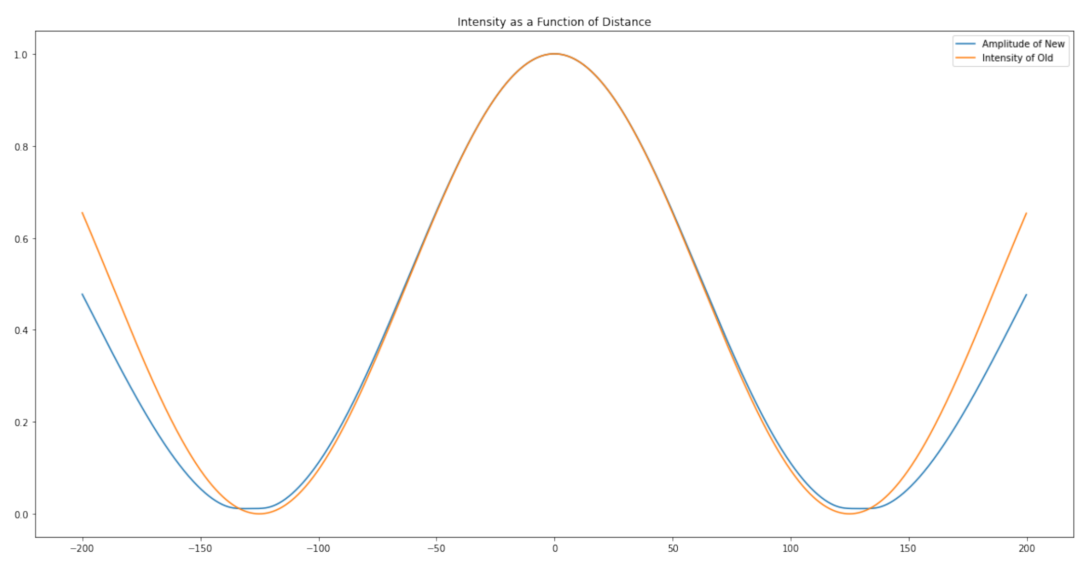
Notice that this is not perfect. This is because the Fourier Transform uses the far-field approximation, but the location of the first minimum isn’t necessarily small enough.
Оригинал в Архива: experiment.pdf