RMPh 2010, Експеримент — Задача 2. Study of the Moiré patterns
3rd Romanian Master of Sciences 2010 Physics – Experimental Tour · 10 т.
Условие
When two transparent layers containing correlated opaque patterns are superposed, a Moiré pattern appears. The simplest Moiré pattern can be observed when a transparency comprising a grid (periodically repeating opaque parallel lines) is superposed onto a paper sheet comprising also a grid as in the Figure 1.
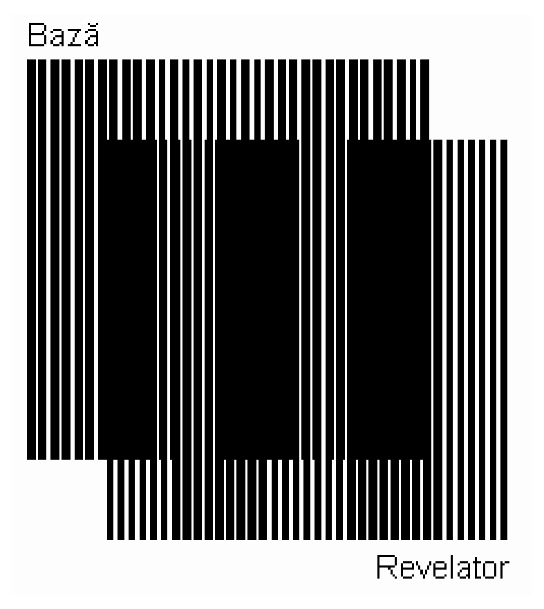
The period of a grid is the space between the axes of two adjacent parallel lines; in a Moiré experiment the difference between the periods of the two grids must be very small.
In what follows, the base sheet will be named “base” and the transparency will be named “revelator”. Let’s denote the period of the “base” by , and the period of the “revelator” by . The image appearing by superposition of the grids outlines periodically repeating dark parallel bands, called Moiré lines. The spacing between the Moiré lines is much larger than the periods of the two grids.
The light areas of the superposed image correspond to the zones where the lines of the two grids overlap. The dark areas of the superposition image, forming the Moiré lines, correspond to the places where a dark line of one grid overlaps with a white space between the lines of the other grid. This can be seen in the Figure 2.
The dark and light Moiré lines are periodically interchanging. In the case shown , so if we start counting layer lines from the point where they overlap, the base layer lines, having a longer period, advance faster than the revelator layer lines, which have a shorter period. By the distance , the base layer lines are ahead of the revelator layer lines by a full period, and the lines of the two layers overlap again.
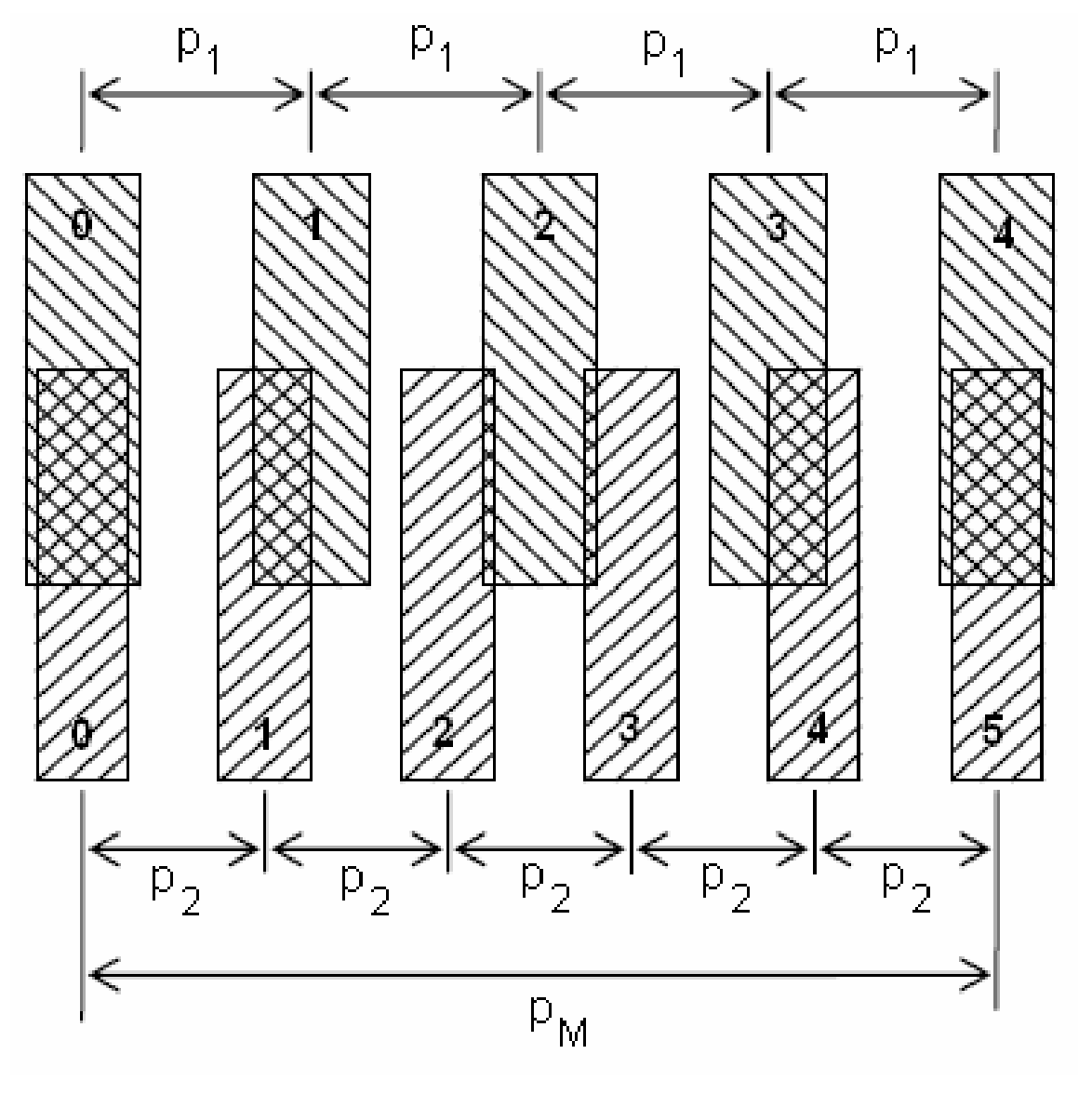
The number of base layer lines contained in the distance is equal to the number of revealing layer lines contained in the distance minus one
that is
The superposition of two layers comprising grids of parallel lines forms an optical image with parallel Moiré lines with a augmented period. The closer the period of the two grids (i.e. the smaller the difference ) the bigger the period of Moiré pattern.
If the situation is reversed and the revelator grid period is longer than the base layer period, the space between the Moiré lines is equal to the absolute value of formula (2).
Moiré patterns are useful in representing fluid flow and potential fields. Problems in optics, wave motion, stress analysis, crystallography, mathematics, and the psychology of perception may also be solved.
Experimental set-up
For experimental problem 2 you receive a kit containing:
1. An expanded Styrofoam board serving as experimental table, allowing the thrusting (pricking) of pins.
2. An envelope containing :
a. A transparency marked “Rigla, raportor, grila 1”. On the transparency it is printed:
i. a protractor;
ii. a ruler with major ticks divided in ten minor ticks; this minor ticks represent the arbitrary unit (a.u.) of the experiment;
iii. a marked grid, whose period is 0.76 a.u.
b. A transparency marked “Rigla, raportor, grila 2”.
c. A paper sheet marked “Rigla, raportor, grila 2”.
d. A paper sheet marked “Rigla, raportor, grila 3”
e. Four clear transparencies. (Attention: you are allowed to write or to draw only on these transparencies).
3. A small plastic bag containing:
a. A few pins.
b. Two different colors markers.
(When you use the transparencies detach them from the protecting paper sheet.)
Experimental Questions
I. Parallel grid (6 т.)
A. Using the transparency marked “Rigla, raportor, grila 1” and the paper sheet marked “Rigla, raportor, grila 2”, a clear transparency, pins and markers, determine in a. u. the period of the grid printed on paper. Write in the appropriate box on the Answer Sheet the value in a. u. of the period of the Moiré pattern. Write in the appropriate box on the Answer Sheet the value in a. u. of the period of the grid printed on paper. [1,5 т.]
B. Using the transparency marked “Rigla, raportor, grila 1 and the paper sheet marked “Rigla, raportor, grila 3”, a clear transparency, pins and markers, determine the period of the grid printed on paper. Write in the appropriate box on the Answer Sheet the value in a. u. of the period of the Moiré pattern. Write in the appropriate box on the Answer Sheet the value in a. u. of the period of the grid printed on paper. [1,5 т.]
C. Test for the possibility of appearance of a Moiré pattern using the transparency marked “Rigla, raportor, grila 2” and the paper sheet marked “Rigla, raportor, grila 2”. In the appropriated box on the Answer Sheet write a comment about the observed image. [1 т.]
D. Examining the grids and using the obtained results, write the values of the periods of grids in the appropriate boxes on the Answer Sheet. [2 т.]
II Rotated grids (4 т.)
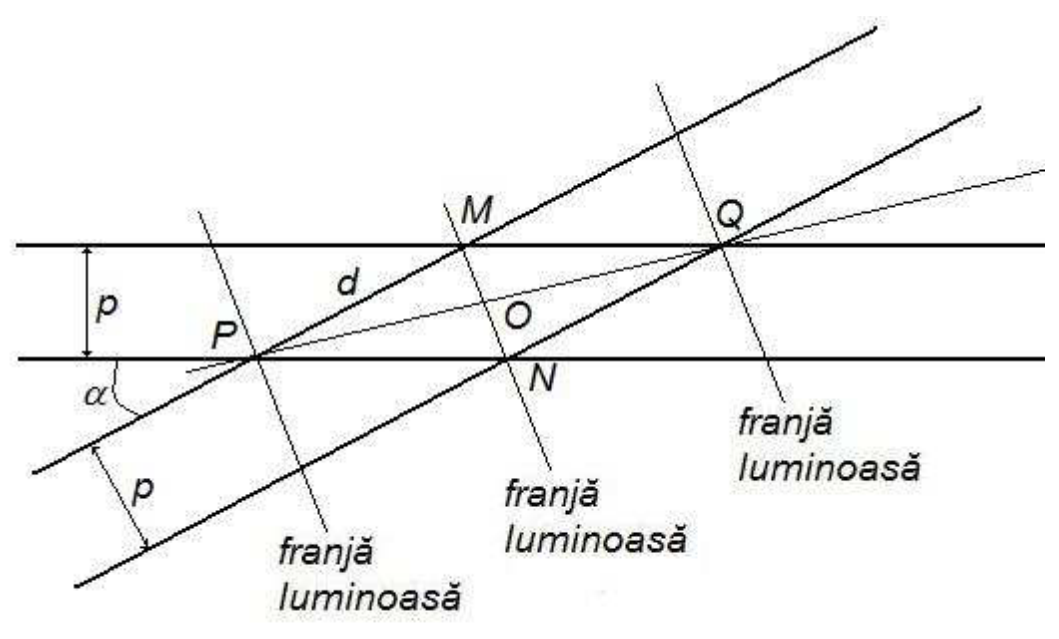
E. Let us consider two grids with the same period , but the two grids are rotated by an angle with respect to each other. Find the expression of the period of the appearing Moiré pattern in terms of and . [2 т.]
F. Using the transparency marked “Rigla, raportor, grila 2” and the paper sheet marked “Rigla, raportor, grila 2”, a clear transparency, pins and markers, measure the period of the Moiré pattern when the angle between the grids increase from to . At least 15 measurements are required. Fill in the Table 1 on the Answer Sheet. [1 т.]
G. Fill in the Table 2 with the theoretical and measured values of the Moiré patterns periods and with the ratio of these two periods. At least 10 set of data are required. [1 т.]
Delia DAVIDESCU – National Center for Assessment and Examination – Ministry of Education, Research, Youth and Sport
Dr. Adrian DAFINEI – Faculty of Physics – University of Bucharest
Answer Sheet
I. Parallel grid
A. The value in a. u. of the period of the Moiré pattern
The value in a. u. of the period of the grid printed on the “Rigla, raportor, grila 2” sheet
B. The value in a. u. of the period of the Moiré pattern
The value in a. u. of the period of the grid printed on the “Rigla, raportor, grila 3” sheet
C. Comment on the observed image
D. The values of the periods of the grids
| “Rigla, raportor, grila 1” a.u. | “Rigla, raportor, grila 2” a.u. | “Rigla, raportor, grila 3” a.u. |
|---|---|---|
| 0,76 a.u. |
E. The expression of the period of the appearing Moiré pattern in terms of and
F. Table 1
| No. | ||
|---|---|---|
G. Table 2
| No. | ||||
|---|---|---|---|---|
Отговори
I. Parallel grid, D. “Rigla, raportor, grila 2”: 0.79 a.u.; “Rigla, raportor, grila 3”: 0.73 a.u.
II Rotated grids, E.
As printed in the evaluation sheet (PO = p·cos(α/2)/sin α).
Решение
Evaluation Sheet
Experimental problem 2
I. Parallel grid
A. For: 1.5p
the value of the period of the Moiré pattern: 23 u.a. 1.0p
the value of the period of the grid marked “Rigla, raportor, grila 2”: 0.5p
B. 1.5p
the value of the period of the Moiré pattern: 23 u.a. 1.0p
the value of the period of the grid marked “Rigla, raportor, grila 3”: 0.5p
C. For: 1.0p
correct commentary regarding the possibility for a Moiré pattern to appear as a consequence of the usage of the grids indicated 1.0p
D. For: 2.0p
the value of the period of the grid marked “Rigla, raportor, grila 2”: 0.79 u. a. 1.0p
the value of the period of the grid marked “Rigla, raportor, grila 3”: 0.73 u. a. 1.0p
II Rotated grids
E. For: 2.0p
(figure) 0.5p
0.5p
0.5p
0.5p
F. For: 1.0p
correctly filling in Table 1 1.0p
G. For: 1.0p
correctly filling in Table 2 1.0p
TOTAL 10p
Оригинал в Архива: experimental_tour_problems_EN.pdf · официални решения: experimental_tour_solutions_EN.pdf