Съдържание
УсловиеExperimental set-upTask No. 1- Measurements on black boxTask No. 2 - Determination of the content of black boxTask No. 3- Characteristics of the elements inside black boxANSWER SHEETExperimental problem no. 2 - Black box (10 points)Task No. 1- Measurements on black boxTask No. 2 - Determination of the content of black boxTask No. 3- Characteristics of the elements inside black boxОтговориРешениеRMPh 2013, Експеримент — Задача 2. Black box
Romanian Master of Physics 2013 — Experimental problem no. 2 - Black box (10 points) · 10 т.
Условие
In a black box are closed electric circuit elements such as: resistor, capacitor, diode, battery, and switches.
YOU ARE NOT ALLOWED TO OPEN THE BLACK BOX!
Determine the type of black box circuit elements and how these elements are related to the four exterior contacts.
Experimental set-up
A. On the workbench you will find:
- An electrically conducting wire with plugs.
- An electrical source.
- A stopwatch.
- A measurement instrument (multimeter) with connecting wires.
- A black box.
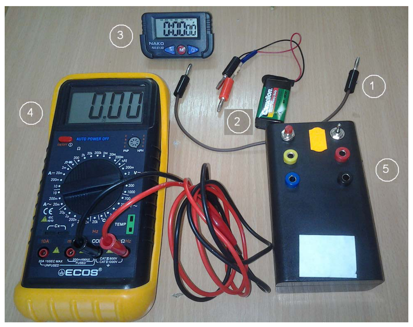
B. Description of equipment to be used
- Connecting wire has plug connectors at ends. It is assumed that their electrical resistance is negligible.
- The electrical source is a battery in series with a resistor having electrical resistance (with a protective role).
- The stopwatch has in its bottom side a set of three buttons – as shown.
The central button marked M will be successively pressed until the timer display will show up 0:00 oo. If you want to measure a time, start timing by pressing the button marked with D (in the bottom right side ). To stop the measurement, press again the button marked with D.
To reset the stopwatch, press the button marked with S (bottom left side).
- The multimeter which has a screen that displays three digits, will be used ONLY as a voltmeter measuring in the domain of 20V. For this, the central rotating function selector of the instrument must be set to 20V. Start the instrument by pressing the red button top left (below the screen). If the instrument is not used for a few minutes, it automatically stops and must be restarted. Measurement is made using two connecting wires from the experimental setup. The plugs of wires will be inserted ONLY in the socket of instruments marked COM or .
- The black box has four connecting sockets with colors red, black, and yellow, blue.
On the top of black box, above the sockets are a pressing switch and a three position switch. The pressing switch has a red button that will be pressed before any measurement. The three positions switch can be placed in the position 1,(where is a green label marked with 1) or in vertical or lateral position (where is a red label marked 0). Under terminal is a label containing the device number. You must write this number on the answer sheet.
It's called "galvanic coupling" the electric connection of circuit elements. It calls "optical coupling" the situation where the light emitted by a device induce modifications of the characteristics of another device; it is assumed that the two devices are not electrically coupled.
The aim of this study is to determine the number of circuit elements of a particular type inside the black box and how these elements are connected. Keep in mind that a diode is a valve for electrons that exhibits low electrical resistance when is forward biased and a high electrical resistance when is reverse biased. A light-emitting diode LED is a diode which emits light when is forward biased. A photo resistor is a resistor whose electrical resistance decreases when illuminated. Keep in mind that inside the black box is a capacitor having capacitance
Task No. 1- Measurements on black box
1.a. Perform measurements allowing to complete table 1.1 of the answer sheet.
For table 1.1, measurement of data will be done with the three-position switch in position 1. [2 т.]
1.b. Perform measurements allowing to complete table 1.2 of the answer sheet.
For table 1.2, measurement of data will be done with the three-position switch in position 0. [2 т.]
Measurements will be made to fill in the answer sheet the tables 1.1 and 1.2 respectively. Fill the Table 1.1 with measured data taken when the three-position switch is in the position 1 and fill the table 1.2 with measured data taken with the three-position switch in the position 0. It will make measurements of voltage between black box terminals, when the black box is coupled with other elements of the experimental set.
Before each measurement the red button of the switch must be pressed.
So,
- If the number 1 is entered in column A, between terminals marked in the column, B, must be connected the electric source with the positive (red) terminal to the terminal written in the first position in column B.
- If the number 2 is entered in column A, between terminals marked in the column B, must be connected the electric source with the negative (black) terminal to the terminal written in the first position in column B.
- If the number 3 is entered in column A, between terminals marked in the column B, must be connected with the wire with negligible electric resistance.
- If the number 4 is entered in column A, terminals marked in the column, B, remain free (without any link).
In columns C, D, E, F, G, H must be entered the read values of the voltages between terminals red - black, red - yellow, red - blue, black - yellow, black - blue and yellow - blue.. Always the first terminal in a given combination must be linked to the terminal COM (black) of the voltmeter.
As an example, the line
| A | B | C | D | E | F | G | H |
|---|---|---|---|---|---|---|---|
| 2 | Red-black | Red-black | Red-yellow | Red-blue | Black-yellow | Black-blue | Yellow-blue |
in table 1.1. must contain the values of the voltage measured, at a time, between terminals red - black, and then between terminals red - yellow, and so on, when the electric battery negative terminal (marked in black) is connected with the first terminal of black box (marked in column B with color red); the electric battery positive terminal (marked in red) is connected with the second terminal of black box (marked in column B with color black)
If, during the measurements is found that the measured voltage varies significantly over time, in the appropriate box in appropriate column (C, D, E, F, G or H) will be written two or three pairs of data (voltage, time); the first pair of data will contain (initial voltage , initial time - "0")
Task No. 2 - Determination of the content of black box
2.a. Draw a sketch of the circuit, to shown how the circuit elements "discovered" inside the black box are connected to the terminals and switches. [1,5 т.]
2.b. Using data from tables, justify briefly the proposed scheme. [1,5 т.]
Task No. 3- Characteristics of the elements inside black box
3.a. Present the characteristics of circuit elements "discovered" inside the black box. [1,5 т.]
3.b. Justify how are the couplings between these elements. [1,5 т.]
© Experimental Problem No. 2 proposed by:
Delia DAVIDESCU, PhD
Ion TOMA
Adrian DAFINEI, PhD
ANSWER SHEET
Experimental problem no. 2 - Black box (10 points)
Task No. 1- Measurements on black box
1.a. Perform measurements allowing to complete table 1.1.
Table 1.1 – The three-position switch in position 1 (green label) — 2,00p
| A | B | C | D | E | F | G | H |
|---|---|---|---|---|---|---|---|
| Red-black | Red-yellow | Red-blue | Black-yellow | Black-blue | Yellow-blue | ||
| 1 | Red-black | ||||||
| 1 | Red-yellow | ||||||
| 1 | Red-blue | ||||||
| 1 | Black-yellow | ||||||
| 1 | Black-blue | ||||||
| 2 | Red-black | ||||||
| 2 | Red-yellow | ||||||
| 2 | Red-blue | ||||||
| 2 | Black - yellow | ||||||
| 2 | Black-blue | ||||||
| 2 | Yellow-blue | ||||||
| 3 | Red-black | ||||||
| 3 | Red-yellow | ||||||
| 3 | Red-blue | ||||||
| 3 | Black - yellow | ||||||
| 3 | Black-blue | ||||||
| 3 | Yellow-blue | ||||||
| 4 |
1.b. Perform measurements allowing to complete table 1.2
Tabelul 1.2 – The three-position switch in position 2 (red label) — 2,00p
| A | B | C | D | E | F | G | H |
|---|---|---|---|---|---|---|---|
| Red-black | Red-yellow | Red-blue | Black-yellow | Black-blue | Yellow-blue | ||
| 1 | Red-black | ||||||
| 1 | Red-yellow | ||||||
| 1 | Red-blue | ||||||
| 1 | Black-yellow | ||||||
| 1 | Black-blue | ||||||
| 2 | Red-black | ||||||
| 2 | Red-yellow | ||||||
| 2 | Red-blue | ||||||
| 2 | Black-yellow | ||||||
| 2 | Black-blue | ||||||
| 2 | Yellow-blue | ||||||
| 3 | Red-black | ||||||
| 3 | Red-yellow | ||||||
| 3 | Red-blue | ||||||
| 3 | Black-yellow | ||||||
| 3 | Black-blue | ||||||
| 3 | Yellow-blue | ||||||
| 4 |
Task No. 2 - Determination of the content of black box
2.a. Draw a sketch of the circuit, to shown how the circuit elements "discovered" inside the black box are connected to the terminals and switches. — 1,50p
2.b. Using data from tables, justify briefly the proposed scheme. — 1,50p
Task No. 3- Characteristics of the elements inside black box
3.a. Present the characteristics of circuit elements "discovered" inside the black box. — 1,50p
3.b. Justify how are the couplings between these elements. — 1,50p
Отговори
Between the red and black sockets: a diode (a light-emitting diode). Between the yellow and blue sockets: a condenser (capacitor) with a push button across it, in series with a resistor (a photo resistance, ≈ 15 kΩ), the three-position switch and an interior battery (2,7 ÷ 3,2 V). There is no galvanic link between the two parts; the LED and the photo resistance are optically coupled.
Summary of the official solution (2.a sketch, 2.b and 3.b).
Решение
Experimental problem no. 2 - Black box - Solution
Task No. 1- Measurements on black box
1.a.
Table 1.1 – The three-position switch in position 1 (green label) — 2,00p
| A | B | C | D | E | F | G | H | Rez | Nr |
|---|---|---|---|---|---|---|---|---|---|
| Red-black | Red-yellow | Red-blue | Black-yellow | Black-blue | Yelow-blue | ||||
| 1 | Red-black | 1,76 | 0 | 0 | 0 | 0 | 0 | 19 | |
| 1 | Red-yellow | 0 | 9,46 | 9÷6 | 8,05 | 8÷6 | 0 | 20 | |
| 1 | Red-blue | 0 | 9÷12 | 9,46 | 8,05 | 8÷12 | 0 | 21 | |
| 1 | Black - yellow | 0 | 0 | 0 | 9,46 | 9÷12 | 0 | 22 | |
| 1 | Black-blue | 0 | 0 | 0 | 9÷12 | 9,46 | 0 | 23 | |
| 2 | Red-black | -9,44 | 0 | 0 | 0 | 0 | (0,0);(1,12) | 7k | 24 |
| 2 | Red-yellow | 0 | -9,44 | -9÷-12 | 0 | 0 | (0,0);(1,23) | 15k | 25 |
| 2 | Red-blue | 0 | -9÷-7 | -9,45 | 0 | 0 | (0,0);(1,23) | 26 | |
| 2 | Black - yellow | 0 | -8,01 | -8÷-11 | -9,44 | -9÷-12 | (0,0);(1,23) | 26 | |
| 2 | Black-blue | 0 | -8÷-5 | -8,01 | -9÷-6 | -9,46 | (0,0);(1,23) | 15k | 28 |
| 2 | Yellow-blue | 0 | 0 | 0 | 0 | 0 | (0,0);(3,10) | To 6 | 29 |
| 3 | Red-black | 0 | 0 | 0 | 0 | 0 | (0,0);(1,23) | 15k | 30 |
| 3 | Red-yellow | 0 | 0 | (0,0);(1,23) | 0 | 0 | (0,0);(1,23) | 15k | 31 |
| 3 | Red-blue | 0 | (0,0);(1,23) | 0 | 0 | 0 | (0,0);(1,23) | 15k | 32 |
| 3 | Black - yellow | 0 | 0 | 0 | 0 | (0,0);(1,23) | (0,0);(1,23) | 15k | 33 |
| 3 | Black-blue | 0 | 0 | 0 | (0,0);(1,23) | 0 | (0,0);(1,23) | 15k | 34 |
| 3 | Yellow-blue | 0 | 0 | 0 | 0 | 0 | 0 | 35 | |
| 4 | 0 | 0 | 0 | 0 | 0 | (0,0);(1,22) | 15k | 36 |
1.b.
Tabelul 1.2 – The three-position switch in position 0 (red label) — 2,00p
| A | B | C | D | E | F | G | H | Rez | Nr |
|---|---|---|---|---|---|---|---|---|---|
| Red-black | Red-yellow | Red-blue | Black-yellow | Black-blue | Yellow-blue | ||||
| 1 | Red-black | 1,77 | 0 | 0 | 0 | 0 | 0 | 1 | |
| 1 | Red-yellow | 0 | 9,45 | 9,45 | 8,03 | 8,03 | 0 | 2 | |
| 1 | Red-blue | 0 | 9,46 | 9,46 | 8,03 | 8,03 | 0 | 3 | |
| 1 | Black - yellow | 0 | 0 | 0 | 9,46 | 9,46 | 0 | 4 | |
| 1 | Black-blue | 0 | 0 | 0 | 9,46 | 9,46 | 0 | 5 | |
| 2 | Red-black | -9,45 | 0 | 0 | 0 | 0 | 0 | 6 | |
| 2 | Red-yellow | 0 | -9,49 | -9,49 | 0 | 0 | 0 | 7 | |
| 2 | Red-blue | 0 | -9,46 | -9,46 | 0 | 0 | 0 | 8 | |
| 2 | Black - yellow | 0 | -8,02 | -8,03 | -9,46 | -9,45 | 0 | 9 | |
| 2 | Black-blue | 0 | -8,02 | -8,02 | -9,46 | -9,45 | 0 | 10 | |
| 2 | Yellow-blue | 0 | 0 | 0 | 0 | 0 | (0,0),(2,5) | 5k | 11 |
| 3 | Red-black | 0 | 0 | 0 | 0 | 0 | 0 | 12 | |
| 3 | Red-yellow | 0 | 0 | 0 | 0 | 0 | 0 | 13 | |
| 3 | Red-blue | 0 | 0 | 0 | 0 | 0 | 0 | 14 | |
| 3 | Black - yellow | 0 | 0 | 0 | 0 | 0 | 0 | 15 | |
| 3 | Black-blue | 0 | 0 | 0 | 0 | 0 | 0 | 16 | |
| 3 | Yellow-blue | 0 | 0 | 0 | 0 | 0 | 0 | 17 | |
| 4 | 0 | 0 | 0 | 0 | 0 | 0 | 18 |
Task No. 2 - Determination of the content of black box
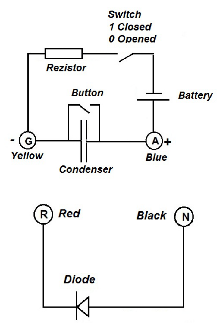
2.a.
2.b. Analyzing the results of measurements in the situation 4, with the switch in the position open, 0,(red label) results that it not any closed electric link between elements. When the switch is in the position 1(green label), between the sockets blue yellow appears a variable tension – that means that in the box it exists an RC circuit and a battery. Because the tension on the yellow - blue sockets the tension increases that mean that between these sockets is coupled the condenser. The fact that pushing the read button the measured tension instantly decreases s at 0, means that the button shorts the condenser, discharging him. Adding the results of measurements for situation 3, results that it not exist any other electric link between these part of the circuit and the red and black sockets.
Analyzing temporal evolution of the tension on Yellow Blue sockets, results that the resistance inserted in the circuit has .
Measurements performed in situations 1 and 2, add to previous observations the fact that the electronic component between the red and black socket has different electric resistance as function of the polarization.
Between the red and black socket it is a diode.
All other observation are consistent with these composition of the black box.
A problem appears in the measurement 22. Calculating the value of electric resistance in the RC circuit for the situation of direct biased diode, the resulting value is half of the previously calculated value of resistance. That allow concluding that the diode is a Light emitting diode and the resistance in RC circuit is a photo resistance whose resistance diminish when illuminated.
In the black box it exists an optical coupling as suggested.
Task No. 3- Characteristics of the elements inside black box
3.a. When a circuit containing a capacitor of capacity C and a resistor of resistance R are coupled to a source of electromotive tension E, the evolution in time of tension on capacitor is
If the electromotive tension and the capacity are known and the tension on capacitor is measured, the value of resistance is
The value of electromotive tension of the exterior battery can be directly measured.
The value of interior battery, is the value „on limit” of the tension on the yellow blue sockets (the terminals of the condenser)
3.b. The values of characteristics of the elements in the black box (and in experimental set up) are
In calculating the values of the resistance, the formula presented above will be used.
© Solution of the Experimental Problem No. 2 proposed by:
Ion TOMA
Delia DAVIDESCU, PhD
Adrian DAFINEI, PhD
Оригинал в Архива: Experimental_Problem_2_Question.pdf · официални решения: Experimental_Problem 2_Solution.pdf