RMPh 2017, Теория, пролетна сесия — Задача 1. Reflection and refraction of light
Romanian Master of Physics 2017
Внимание: Бележка към темата
The archive catalogue attaches T1_sol.pdf to the unrelated October 2017 problem “Two paradoxes”. Its nine original pages instead contain the full author solution to this spring problem, “Reflection and refraction of light”: A1–A3, B1, B2.1–B2.4, B2.5.1 and B2.5.2. The printed key has been matched to this existing whole problem. Its numerical values, notation and source defects are retained literally.
Условие
A. An interesting prism
The main section of a glass prism, situated in air , has the form of a rhomb with . A thin yellow beam of monochromatic light, propagating towards the prism, parallel with the diagonal AC of the rhomb, is incident on the face AB (Fig. 1). The beam is totally reflected on the faces AD and DC, then emerges through its face BC. For the yellow radiation, the refraction index of the glass is .
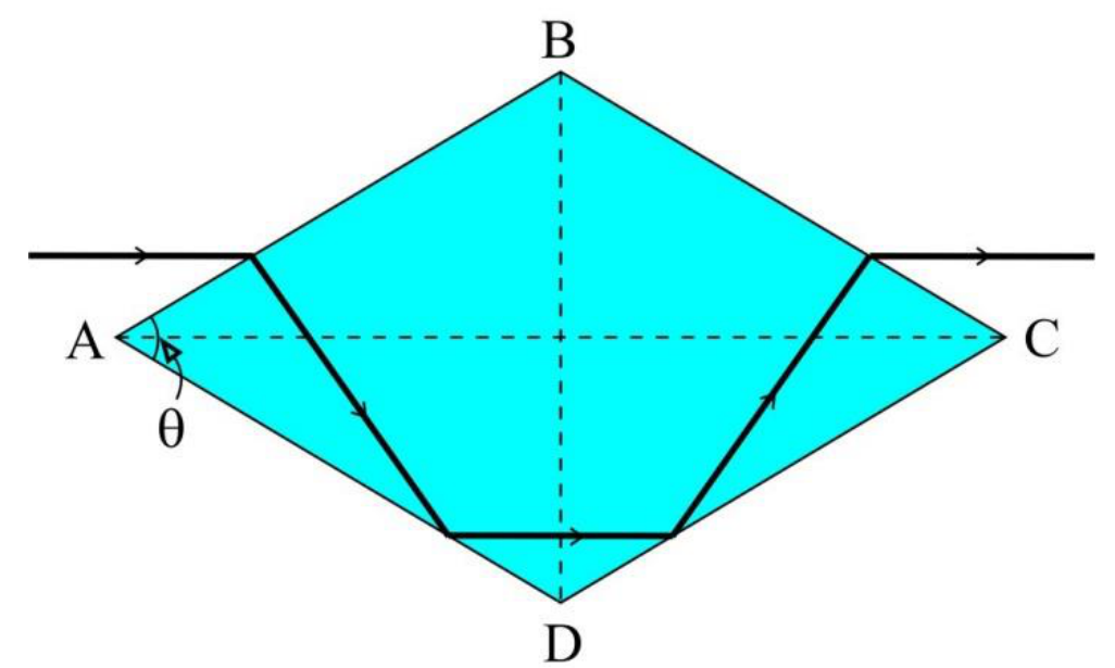
Fig. 1
A1 Derive the mathematical expression for the angle as a function of the refraction index of the prism, such that the total deviation of the beam that exits the prism to be zero. Under the above condition, calculate the numerical value of in degrees and minutes, if . [2,25 т.]
The prism with determined above and the direction of the incident beam remain fixed, but the nature of the light radiation changes, being formed now of the yellow doublet of the mercury. The two wavelengths have the values 579.1 nm, respectively 577 nm. The refraction indices of the glass for these wavelengths are , respectively , where . The light rays that exit the prism enter longitudinally into an astronomical telescope adjusted for infinite distance.
A2 Derive the mathematical expression for „the angular distance” between the two images seen through the telescope (first as a function of and , then as a function of and ) and calculate its numerical value. [2 т.]
A3 If the focal distance of the telescope’s objective is , derive the linear distance between the two images, seen in the focal plane of the objective and calculate its numerical value. [0,5 т.]
B. Refraction, but…mostly reflection
B1. Total reflection in geometrical optics
Total reflection occurs when light travels from a medium with refractive index to another one, with the refractive index , at an incidence angle , where is the critical value of the incidence angle, called limit angle, beyond which there will be no refracted light. At total reflection, the entire energy of the incident light beam goes to the reflected beam.
B1 Derive the mathematical expression for the limit angle [0,25 т.]
B2. Total reflection in electromagnetic optics
Electromagnetic optics proves that, besides being totally reflected, the incident light beam also penetrates the less refringent medium as an evanescent wave.
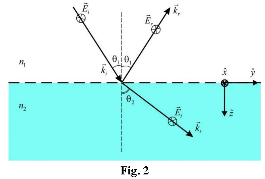
The characteristics of the reflected and the refracted light beams depend on the angle of incidence, as well as on the orientation of the electric field of the light wave (called polarization). For simplicity, let us consider that the electric field intensity is perpendicular on the incidence plane, as represented in Fig. 2. The indices , , and refer to the incident, reflected and transmitted properties of light waves while is the wave vector, giving the light propagation orientation. Moreover, , and are the unit vectors of the chosen Cartesian reference frame.
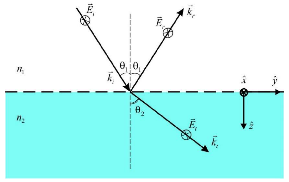
Fig. 2
Physical note: The perturbation produced by a plane, monochromatic wave in a point in space at a certain moment of time can be written as , or, to simplify calculations, in the complex form , where , and then taking only the real part of the result.
Mathematical note: For the complex number , is the real part and is the imaginary part. It can be written as
where is the modulus of the complex number and .
B2.1. Evanescent wave
B2.1 Knowing that the incident wave is a plane and monochromatic one, characterized by the equation , prove that the mathematical expression for the evanescent wave is and derive the exact expression for the attenuation coefficient as a function of the incidence angle , the limit angle , and the wavelength of the incident wave. Also, derive the exact expression for the phase of the evanescent wave. [1,5 т.]
B2.2. Penetration depth
B2.2 Derive the mathematical expression of the distance from the interface at which the amplitude of the evanescent wave is times smaller than at the interface, as a function of the incident wavelength and calculate its numerical value. The first medium is glass , the second is air , and the incidence angle of light is . [0,5 т.]
B2.3. The phase speed of the evanescent wave
B2.3 Derive the mathematical expression for the ratio , where is the phase speed of the evanescent wave and - the phase speed of the incident wave, and compute its numerical value for the case of the incidence angle of light of . [0,75 т.]
B2.4. The energy transferred from the incident wave to the totally reflected wave
For any value of the incidence angle, the relationship between the amplitude of the field of the reflected wave and that of the incident wave was derived by the French physicist Augustin Fresnel (1788 – 1829):
Physical note: If the perturbation produced by a wave in a point in space at a given moment is expressed using complex numbers, then the wave intensity has the mathematical expression , where is the complex conjugate of the complex number . Here is the vacuum permittivity and is the speed of light in vacuum.
B2.4 Prove that the totally reflected wave has the same intensity as the incident wave. [0,5 т.]
B2.5. The Goos – Hänchen effect
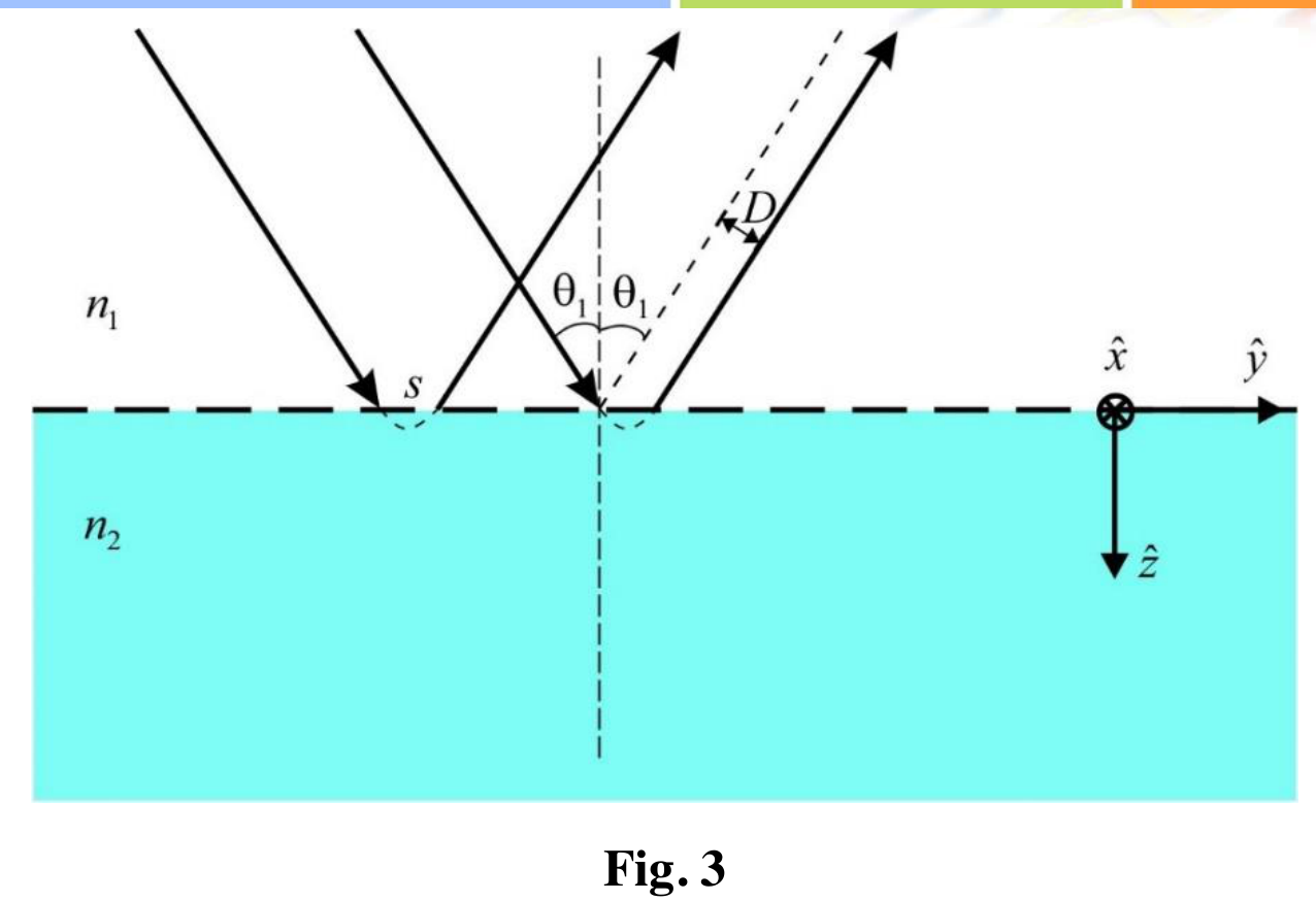
When an incident wave beam with a finite cross section undergoes total reflection at an interface between two media, the totally reflected wave beam is laterally displaced, on a distance (see Fig. 3), that was measured for the first time by Goos and Hänchen in 1947. In Fig. 3, the displacement along the surface is , and the Goos – Hänchen shift is the lateral shift indicated in the diagram. This is the Goos – Hänchen effect. The explanation of this lateral shift is based on the appearance of the evanescent wave at the interface and its propagation parallel to the interface.
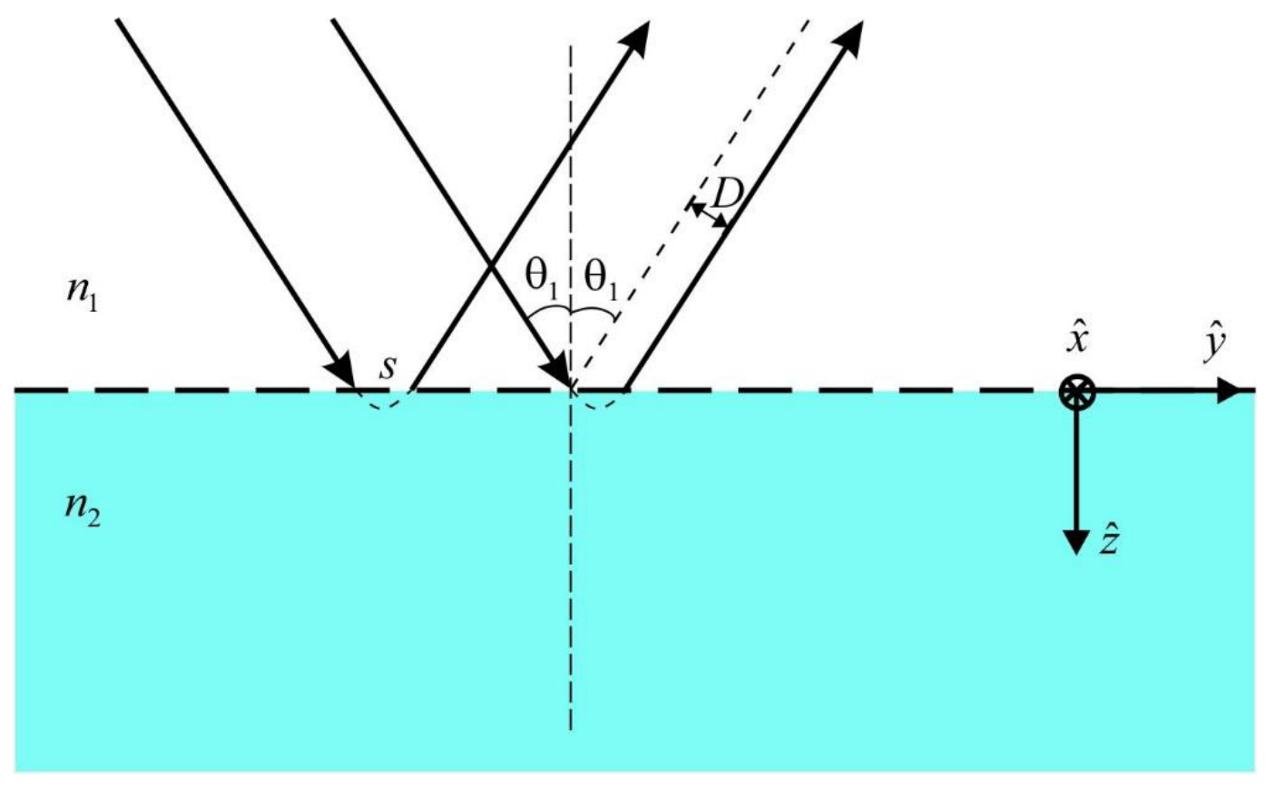
Fig. 3
B2.5.1. The lateral shift
B2.5.1 Derive the mathematical expression for the Goos – Hänchen lateral shift , admitting that the phase difference between the totally reflected wave and the incident one is zero at the interface. Consequently, compute the numerical value of the displacement along the interface as a function of the wavelength of the incident light, if the first medium is glass , the second is air , and the incidence angle of light is . [1 т.]
B2.5.2. Time needed for the total reflection
An alternative explanation of the Goos – Hänchen shift can be given in terms of the time delay associated with the scattering of a radiation pulse at the interface. The incident radiation pulse is not scattered instantaneously by the surface, but reemerges into medium 1 after a time delay , during which the pulse propagates parallel to the surface and is displaced by the distance .
B2.5.2. Derive the mathematical expression for the time delay and calculate its value if the first medium is glass , the second is air , the incidence angle of light is , and the monochromatic radiation has the wavelength . The light speed in vacuum is . [0,75 т.]
proposed by
Prof. Florea ULIU, PhD
Department of Physics, University of Craiova, ROMANIA
Assoc. Prof. Sebastian POPESCU, PhD
Faculty of Physics, Alexandru Ioan Cuza University of Iași, ROMANIA
Решение
A. An interesting prism
The main section of a glass prism, situated in air , has the form of a rhomb with . A thin yellow beam of monochromatic light, propagating towards the prism, parallel with the diagonal AC of the rhomb, is incident on the face AB (Fig. 1). The beam is totally reflected on the faces AD and DC, then emerges through its face BC. For the yellow radiation, the refraction index of the glass is .
A1
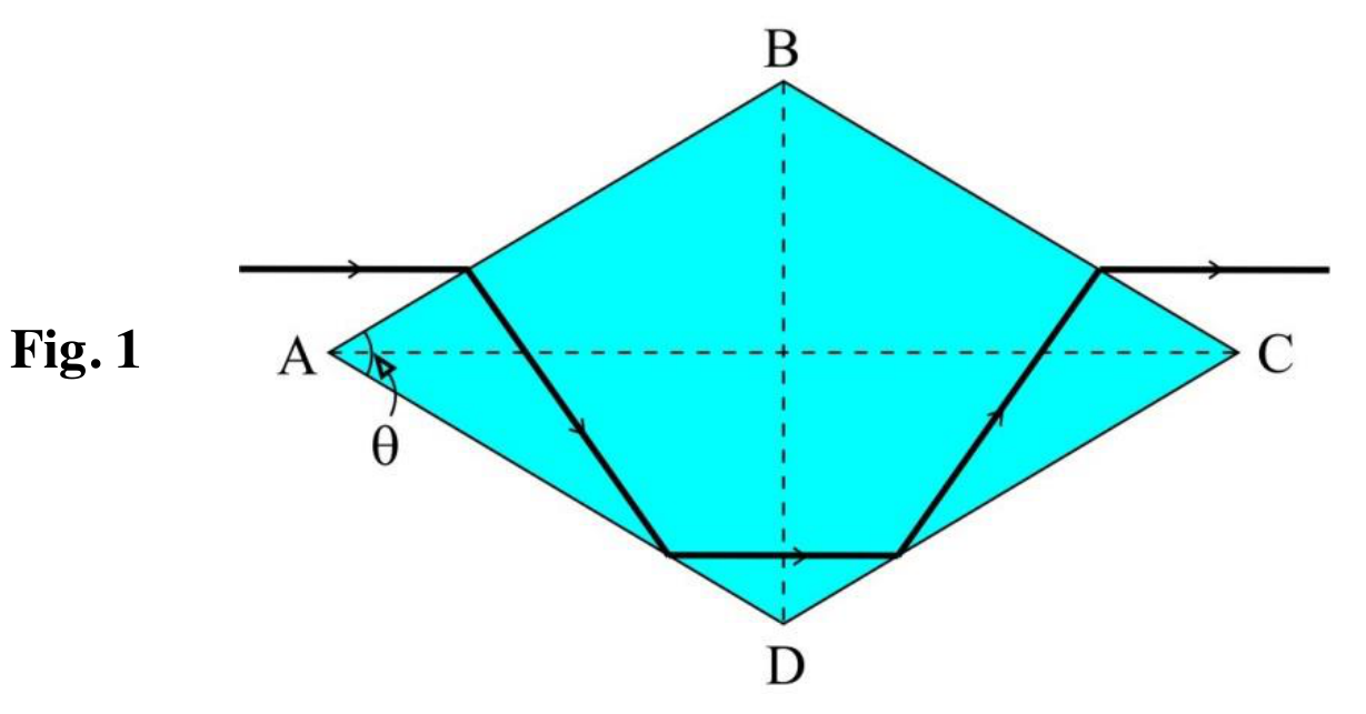
The total deviation is zero only if . This means that and (symmetrical path inside of the rhombic prism). Therefore . (0.25 p)
From the figure below, and .
In the triangle : , so that . (0.25 p)
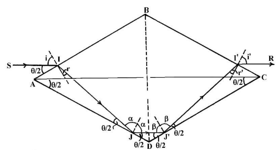
On the other hand, . (0.25 p)
The refraction law (Snell–Descartes) is , or . (0.50 p)
Since
the refraction law becomes . The solution (i.e. ) cannot be accepted as unphysical, so the physical solution is
i.e., . (0.25 p)
A2
We have a fixed angle of incidence and two angles of refraction and , corresponding to and . From we can write .
On the other hand, from , we can write .
Because (or , as in the text of the question) is a very small (infinitesimal) quantity, we can approximate and , but with and . (0.50 p)
We will demonstrate later (see Note below) that .
Now, let us determine the angle between the two emergent rays of light, namely , obtaining
The final result is
We know the mathematical expression of and, after a little algebra, can be expressed in another form, namely
Numerically: (or ). (0.25 p)
Note: In the triangle , we write that the sum of inner angles is (radians), namely , i.e. (for a given rhombic prism, with fixed ). Therefore , where (see the triangle ) and (see the triangle ). Since is fixed (our situation) and so that . (0.25 p)
A3
Numerically: . (0.50 p)
B. Refraction, but…mostly reflection
B1. Total reflection in geometrical optics
When the incidence angle reaches the limit angle , the refraction angle will be . In this case, the second Snell’s refraction law gives , so
B2. Total reflection in electromagnetic optics
Electromagnetic optics proves that, besides being totally reflected, the incident light beam also penetrates the less refringent medium as an evanescent wave.
The characteristics of the reflected and the refracted light beams depend on the angle of incidence, as well as on the orientation of the electric field of the light wave (called polarization). For simplicity, let us consider that the electric field intensity is perpendicular on the incidence plane, as represented in Fig. 2. The indices , , and refer to the incident, reflected and transmitted properties of light waves while is the wave vector, giving the light propagation orientation. Moreover, , and are the unit vectors of the chosen Cartesian reference frame.
Physical note: The perturbation produced by a plane, monochromatic wave in a point in space at a certain moment of time can be written as , or, to simplify calculations, in the complex form , where , and then taking only the real part of the result.
Mathematical note: For the complex number , is the real part and is the imaginary part. It can be written as
where is the modulus of the complex number and .
B2.1. Evanescent wave
For the transmitted wave
where
Since
because , under these conditions the electric field of the transmitted wave can be written as
The sign in the first exponential has no physical significance because there is no wave at appreciable distances from the interface. In conclusion, the electric field of the transmitted (evanescent) wave has the form
where is the attenuation coefficient of the evanescent wave and is the wave’s phase. This result shows that the wave travels along the interface (along direction) and that it is attenuated in the direction (perpendicular on the interface).
Because
then
B2.2. Penetration depth
B2.3. The phase speed of the evanescent wave
Considering the phase of the evanescent wave, its phase speed is
so the requested ratio is
B2.4. The energy transferred from the incident wave to the totally reflected wave
Since
then
For any complex number of the same form we can write
In conclusion , where
Under these conditions, the intensity of the totally reflected wave will be
B2.5. The Goos–Hänchen effect
When an incident wave beam with a finite cross section undergoes total reflection at an interface between two media, the totally reflected wave beam is laterally displaced, on a distance (see Fig. 3), that was measured for the first time by Goos and Hänchen in 1947. In Fig. 3, the displacement along the surface is , and the Goos – Hänchen shift is the lateral shift indicated in the diagram. This is the Goos – Hänchen effect. The explanation of this lateral shift is based on the appearance of the evanescent wave at the interface and its propagation parallel to the interface.
B2.5.1. The lateral shift
From Fig. 3, it follows that .
If in the incidence point for the incident wave, on the interface, the phase of its electric field is , then, at the starting point, for the totally reflected wave its phase is
With , and knowing that , we obtain
Finally,
The numerical value of is .
B2.5.2. Time needed for the total reflection
proposed by
Prof. Florea ULIU, PhD — Department of Physics, University of Craiova, ROMANIA
Assoc. Prof. Sebastian POPESCU, PhD — Faculty of Physics, Alexandru Ioan Cuza University of Iași, ROMANIA
Original blank answer sheet — page 6
The original answer sheet is blank; these are requested answer spaces, not supplied answers.
| Task | Mathematical expression | Numerical value |
|---|---|---|
| A1 | ||
| A2 | and | |
| A3 | ||
| B1 |
Original blank answer sheet — page 7
| Task | Mathematical expression | Numerical value |
|---|---|---|
| B2.1 | and | |
| B2.2 | ||
| B2.3 |
B2.4 has a large empty derivation box which continues onto page 8.
Original blank answer sheet — page 8
| Task | Mathematical expression | Numerical value |
|---|---|---|
| B2.5.1 | ||
| B2.5.2 |
Оригинал в Архива: RMPh2017Q1ENG.pdf · официални решения: T1_sol.pdf