RMPh 2024, Теория — Задача 3. Q3. Polarization and Diffraction
Romanian Master of Physics 2024 · 10 т.
Условие
A. A beam of natural (unpolarized) light, with an intensity , passes through two identical polaroids, placed one after the other one.
a. If the polaroids are ideal and the angle between their transmission axes is , calculate the intensity of the emergent beam. [1 т.]
b. If the two polaroids are non-ideal and the transmission axis of one is rotated with respect to the other, the ratio of the maximum emergent intensity to the minimum emergent intensity is . Calculate the degree of polarization of the light passing through the two polaroids when their transmission axes are parallel. [2 т.]
B. A diffraction aperture is formed by two semi-infinite planes, and , that have different optical properties. A parallel, coherent beam of monochromatic light falls at normal incidence on this aperture. If the intensity of this beam is , calculate the intensity at point P on the screen (see figure 1) for the following configurations.
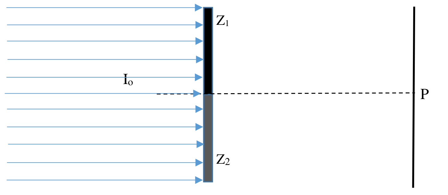
The beam is unpolarized for the following:
c. transparent, opaque; [1 т.]
d. ideal polaroid, opaque; [1 т.]
e. , ideal polaroids with transmission axis with mutually perpendicular axes; [1 т.]
f. transparent, ideal polaroid; [1 т.]
g. , non-ideal polaroids with transmission axis with mutually perpendicular axes (The polaroids are identical and have the amplitude transmission coefficients: 1. parallel to the transmission axis, ; and 2. perpendicular to the transmission axis, . [1 т.]
C. A retarder plate is an optical device used to alter the polarization state of light beams. These plates are typically made from anisotropic materials such as calcite or quartz crystals, which possess an axis of high symmetry called the optic axis. When an incoming light wave enters the retarder plate, it splits into two waves at the entrance: the o-wave (ordinary), with the electric field perpendicular to the optic axis, and the e-wave (extraordinary), with the electric field parallel to the optic axis. Due to their different refractive indices, the plate introduces a phase difference between these waves. If the phase difference is (or an odd multiple of ), the plate functions as a half-wave plate. When a linearly polarized wave enters a half-wave plate, the emerging wave becomes linearly polarized symmetrically about the optic axis of the plate (crystal axis). See Figure 2 for a visual representation.
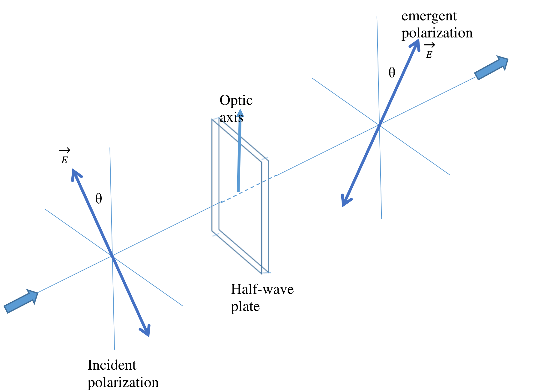
The beam is polarized for the following:
h. transparent, half-wave plate, the angle between the polarization direction and optical axis of half-waveplate is ; [1 т.]
i. half-wave plate, half-wave plate, the optical axes of the two half-waveplates perpendicular to each other. [1 т.]
Note: Any optical path difference due to the optical thickness of the two adjacent areas can be neglected (it is considered that they are compensated in the device).
Lecturer Marian Cornel BAZAVAN, PhD
University of Bucharest
Faculty of Physics
Отговори
a.
b.
c.
In the official solutions this result is printed under the labels c. and d.
d.
Printed under label e. in the official solutions.
e.
Printed under label f. in the official solutions.
f.
Printed under label g. in the official solutions.
g.
Printed under label h. in the official solutions.
h.
Printed under label i. in the official solutions.
i.
Printed under label j. in the official solutions.
Решение
Q3
a. (Malus law) — 0.5 pt
— 0.5 pt
b. Let and represent the energetic transmission coefficients of the polaroids parallel and perpendicular, respectively, to the transmission axis.
Parallel polaroids — 0.5 pt
Perpendicular polaroids — 0.5 pt
The degree of polarization after a single polaroid:
0.5 pt
The degree of polarization after two parallel polaroids:
0.5 pt
c. — 0.5 pt
d. — 0.5 pt
e. — 0.5 pt
— 0.5 pt
f. ; — 0.5 pt
— 0.5 pt
g. ; — 0.5 pt
— 0.5 pt
h. ; — 0.5 pt
— 0.5 pt
i. After the linearly polarized light goes through the half-wave plate, the light is still linearly polarised in a direction symmetrical to the optical axis of the half-wave plate. The contributions of the two areas will be in phase, but the angle between the two polarization directions at P will be : — 0.5 pt
0.5 pt
j. After the light goes through the two areas we have two beams that will be “out of phase”. (the angle between the two components at P will be ): — 0.5 pt
. — 0.5 pt
Оригинал в Архива: Q3_ENG.pdf · официални решения: Q3sol.pdf