WoPhO 2011, Теория — Задача 2. Why Maglev Trains Levitate
IPEKA Problem — Theoretical 2: Why Maglev Trains Levitate
Условие
Maglev is a technology for magnetic suspension (levitation) and propulsion of trains or other vehicles. Since there is no friction force between the train and the rails, Maglev trains reach record velocities approaching 600 km/h.
There are three types of Maglev systems – EMS (Electromagnetic Suspension), EDS (Electrodynamic Suspension), and the experimental Inductrack technology. In this problem you are going to explore the physical principles of Inductrack suspension on a simplified model of a Maglev train. The principle of magnetic propulsion will not be considered here because it has a lot in common with the physics of magnetic levitation.
Shown in Figure 1 is a schematic side view of an Inductrack train-car. When at rest or moving at a low speed, the car lies with its wheels on the rails like any ordinary train. The car, however, detaches from the rails at a specific takeoff velocity due to the system described below: two long parallel arrays of permanent cubic-shape magnets of size , each is located at the bottom of the car. The magnetic dipole moments of the neighboring magnets are tilted at an angle of relative to each other (the so called Halbach array). As a result a static magnetic field is produced below each array with components of the magnetic field given by the equations:
where the -coordinate is measured from the rear end of the car in the direction of motion and -coordinate from the bottom of the car in a downward direction. The parameter is the wavenumber of the magnetic field. The amplitude of the magnetic field is .
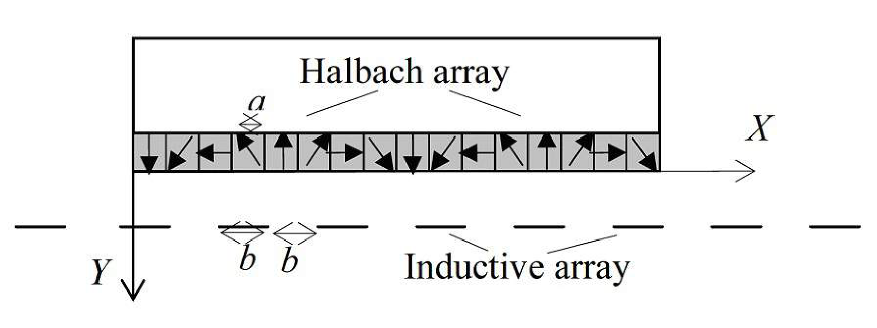
Two inductive arrays of horizontal rectangular wire frames of the same width as that of the permanent magnets are arranged along the rail as seen from the top view in Figure 2. The length of the inductive frames as well as the distance between them is . Each inductive array is located below the corresponding Halbach array at a distance corresponding to the -coordinate of the inductive array (see Figure 1). Assume that the equations 1 and 2 for the components of the magnetic field hold only for the inductive frames, which are located below the car, while the magnetic field outside the car area is strictly zero.
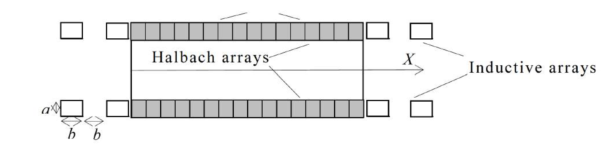
Note: In the real Inductrack trains, the frames of the inductive array are electrically connected and form a continuous ladder-like array. In order to simplify the theoretical consideration, we use a simplified model shown in Figure 2.
Helpful mathematics formulas:
In parts 1-2 assume that the train car is infinitely long (i.e. equations 1 and 2 hold for all values of the -coordinate)
1 Electromotive force in the inductive wires
1(a) Derive a relationship between the wavenumber of the magnetic field and the lateral size of the cubic magnets in the Halbach array . Calculate numerically. [0,3 т.]
1(b) Suppose that the train moves with a constant velocity in the positive direction of the -axis. Consider an inductive frame whose center in the initial moment () is located below the car at a point of coordinate relative to the car. Derive an expression for the electromotive force (EMF) induced in the frame as a function of the time and the other parameters already defined. [1,5 т.]
1(c) What is the angular frequency of the induced EMF. [0,4 т.]
2 Current in the inductive wires
Each frame in the inductive array is characterized by a self-inductance and a resistance . The mutual inductance between different frames is negligible compared to . The current induced in the frame varies with time according to the equation:
2(a) Obtain expressions for the amplitude and the phase-shift of the alternating current induced in the frame.
Note: The positive direction of circulation of the induced current in the frame is related to the positive direction of the -axis according to the right-hand rule. [2 т.]
3 The dynamics of the train
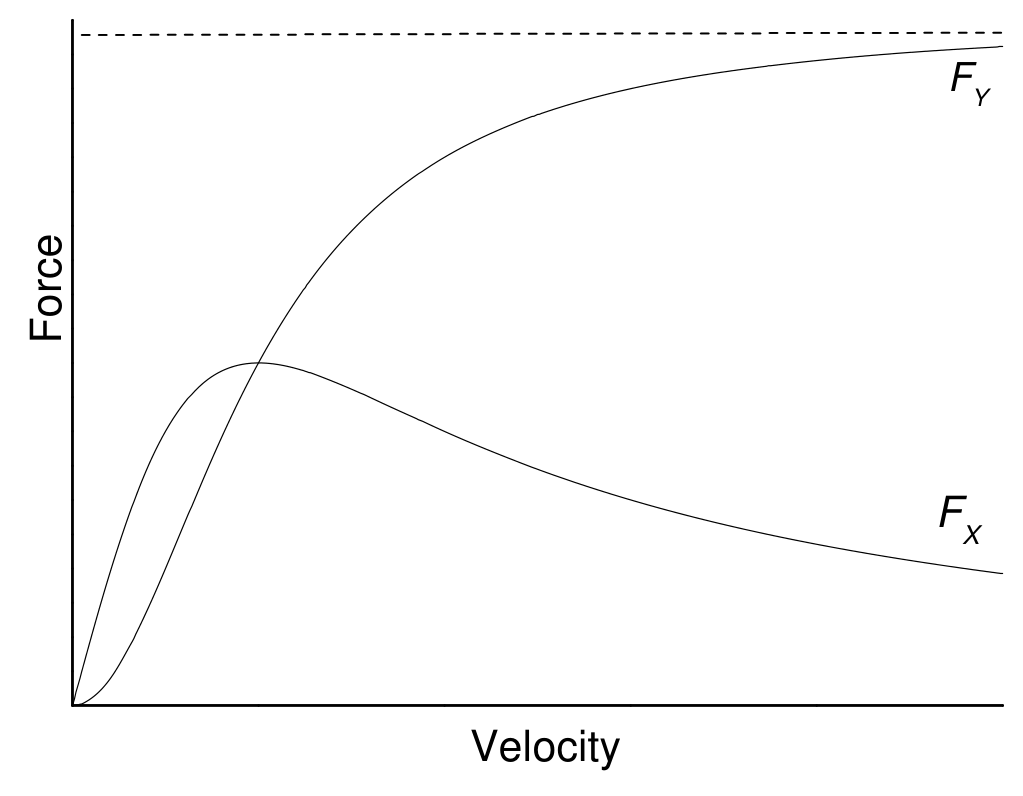
3(a) Derive formulas for the time-averaged components and acting on a single inductive frame in terms of velocity , the distance between the Halbach array and the inductive array , and the others parameters already defined. Sketch qualitative graphs of and versus train velocity for a fixed value of the distance . [3 т.]
3(b) Consider a train-car of a large but finite length (). Derive expressions for the magnitude of the total lift (vertical) and drag (horizontal) forces and acting on the car. [1,2 т.]
3(c) For a given value of , what is the minimum aspect ratio for which the lift force is maximum for given values of the distance , velocity , resistance , and the inductance . [1 т.]
Consider a train-car of length and mass . Assume that the aspect ratio corresponds to the optimal value found in 3(c). The inductance and the resistance of the inductive frames are and respectively. The acceleration due to gravity is . Assume that the distance between the Halbach array and the inductive array is , when the train is at rest.
3(d) Obtain an expression and calculate the takeoff velocity , the velocity at which the train detaches from the rails. [0,3 т.]
3(e) What is the distance between the train and the rails at an operating velocity of ? [0,3 т.]
Отговори
1(a)
1(b)
1(c)
2(a)
The official solution calls the phase-shift φ instead of ψ.
3(a)
3(b)
3(c) 2.968
3(d)
3(e)
Решение
Solution. Why Maglev trains levitate?
Task 1. The wavelength of the magnetic wave corresponds to the spatial period of the Halbach array:
Therefore, the wavevector of the wave is:
or numerically:
Task 2. There are two approaches for obtaining the EMF depending on the choice of the system of reference.
I. A reference system fixed to the Earth
A point, having at time a coordinate relative to the Earth, has a “shifted” coordinate relative to the train. Therefore the components of the magnetic induction relative to the Earth depend on the spatial coordinates and the time according to the equations:
Since relative to the Earth the -coordinate of the given inductive frame spans a fixed interval , the magnetic flux through the frame is:
According to the Faraday’s law of magnetic induction, the induced EMF is:
or
where the circular frequency of the induced EMF is:
II. A reference system connected to the car
In this system the magnetic wave is static but the inductive frame moves with velocity relative to the field. Therefore, the -coordinate of the center of the frame relative to the train is . In that case an EMF is induced along any small element of the frame:
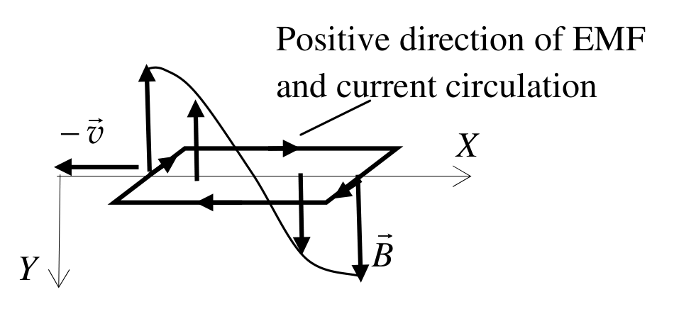
The EMF is induced only along the two sides of the frame, which are perpendicular to the -axis (see Figure S1). Taking into account that the -coordinate of these two sides are , the total EMF in the frame is:
After simplification we obtain the same result as above:
Task 3. The parameters of the induced current could be obtained in two equivalent ways.
I. We set up the Kirchhoff’s equation for the conductive frame:
where is the amplitude of the induced EMF. We substitute into that equation the time dependence of the current:
Consider two moments of time when the phase of the induced EMF is 0 and respectively. Thus, we obtain a set of two equations:
and
Finally we get:
and
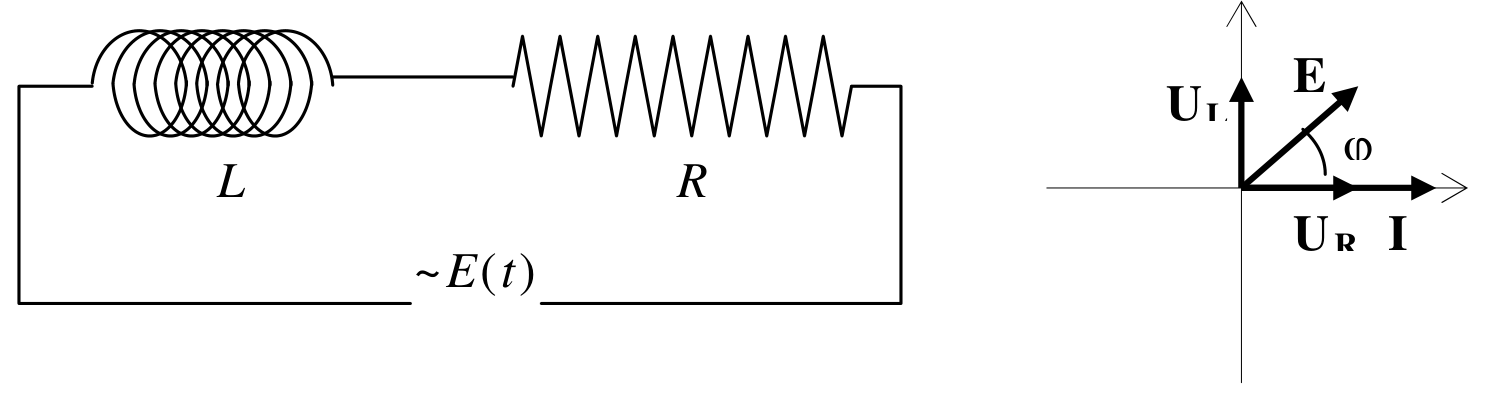
II. The inductive frame is equivalent to a circuit of series-connected inductance and an Ohmic resistance as shown in Figure S2. We consider the rotating-vector diagram for the current and voltage drops and across the inductance and the resistance respectively (see Figure S2). The amplitudes of the voltage drops are connected to the amplitude of the current through:
and
It follows from the diagram that the amplitude of the EMF is given by:
Therefore, the amplitude of the current is:
It is evident from Figure S2 that:
The “–“ sign means that the current is in retard relative to the induced EMF.
Task 4. As it follows from Figure S1 the vertical component of the force acting on the inductive frame is:
The time-average of that function is:
By taking into account the expressions for , and , and the relation we finally obtain:
Concerning the horizontal component of the force, we may take an advantage by using the relation
where
is the average power dissipated by the current in the frame. By using the expression for we obtain:
Qualitative graphs of the two functions are shown in Figure S3.
Points should be awarded for the following details:
- A clear indication that the vertical component of the force tends to a specific limit as the velocity increases.
- The horizontal component of the force has a maximum for a specific velocity.
Task 5. According to the Newton’s third law any single inductive frame exercises on the train a vertical force , i.e. a force directed upward, against the gravity. Similarly, any frame acts on the car with a horizontal force in the direction opposite to the direction of motion. Since there are:
frames below the car area, the magnitudes of the lift and the drag forces are respectively:
By introducing the aspect ratio and noticing that the problem of maximization of the lift force is equivalent to finding a maximum of the function:
After taking a first derivative of the condition for a maximum reduces to solving the equation:
Since in the point of intercept of the two sides of the equation, the tangent function has bigger slope than the linear function, it is convenient to rewrite the equation in a form that allows an iterative solution:
By starting with a trial value, e.g. , we obtain the following convergent series of approximations:
| 1 | 1.6954 | 7 | 2.9658 |
| 2 | 2.3597 | 8 | 2.9674 |
| 3 | 2.7400 | 9 | 2.9679 |
| 4 | 2.8923 | 10 | 2.9680 |
| 5 | 2.9440 | 11 | 2.9681 |
| 6 | 2.9606 | 12 | 2.9681 |
Therefore, up to a precision of 4 significant digits, the optimal aspect ratio is:
Task 6. For the optimal aspect ratio and by taking into account that the expression for the lift force simplifies:
For the train detaches at a velocity such that , i.e.
For the parameters specified:
For greater velocities the train levitates at a distance above the rails such that the equilibrium condition is satisfied:
Therefore, the gap between the wheels and the rails at a velocity of 360 km/h (100 m/s) is:
Оригинал в Архива: WoPhO_2011_Q12.pdf · официални решения: WoPhO_2011_S12.pdf