WoPhO 2013, Теория — Задача 1. Induction Motor
Problem Induction Motor — Deadline April, 1 2013
Условие
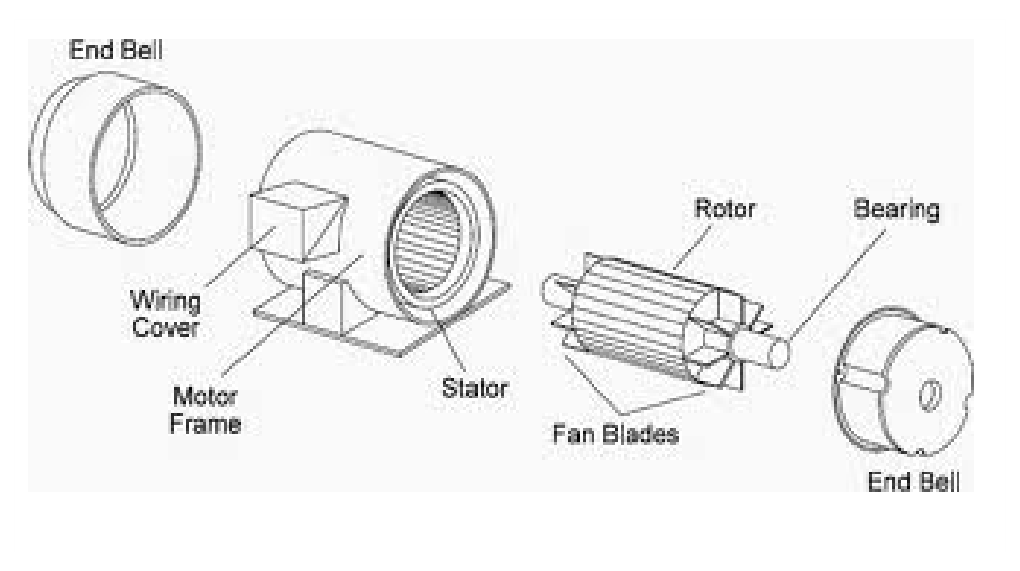
Induction (or asynchronous) motors are the simplest and most reliable electric motors. They are powered by alternating current, and they do not contain commutators, slip rings or brushes. They consist of a stator and a rotor (see fig. 1). The stator is a fixed set of coils, which produces a rotating magnetic field in the plane perpendicular to the axis of the motor. The rotor is just a cage, i.e., a set of closed metallic loops attached to the axis of the motor. The rotating magnetic field produced by the stator induces electric current in the loops of the cage, which behave as magnetic dipoles, and interact with the external field of the stator. As a result, a torque is exerted on the rotor, and it starts rotating.
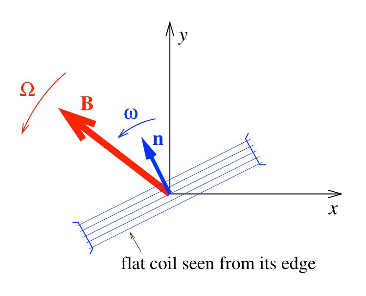
In a simplified model (see fig. 2) we assume that the magnetic induction vector produced by the stator is rotating in the plane at a constant angular velocity , and it has a constant magnitude . The axis of the rotor is in the direction. The rotor is assumed to be a flat coil of area , winding number , Ohmic resistance and self inductance . The vector perpendicular to this coil is rotating also in the plane.
Stationary operation
First we study the stationary operation of the motor, when its angular velocity and torque are constant. As we shall see, when the motor is loaded, its angular velocity gets smaller than . It is convenient to characterize this shift by the slip
which is a dimensionless number between 0 and 1.
Stationary operation at small load
a) Assume that the load is small, so the slip . Determine the time average of the torque exerted by the motor as a function of the slip . (Use reasonable neglections.)
Stationary operation at arbitrary load
b) Determine the average torque as a function of an arbitrary slip value between 0 and 1.
c) Assume that . Sketch the graph of the function .
d) Find the maximal stationary torque and the corresponding slip .
Efficiency
e) Determine the efficiency of the motor as a function of the slip . (Assume that there is no energy loss due to friction, radiation.)
Stability
f) Assume that the motor is connected to an equipment (load) which has a linear characteristics, so for a stationary angular velocity a torque is needed, where is a positive constant. Determine graphically the stable and unstable operation points on the graph obtained in question c) for different -s.
Negative slip
g) Do the negative slip values have any physical meaning? If yes, what? If no, why?
Отговори
a)
First-order result in , obtained from the general expression by neglecting the term.
b)
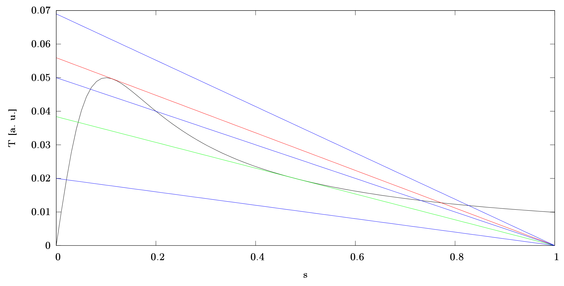
c) Introducing , . For , the graph of on rises sharply from 0, peaks near , then decreases slowly, ending at (not 0) at (see solution figure).
d)
Valid when ; if then and .
e)
f) The operating slip solves . A point is stable when . For , the cubic condition gives boundary slips and : operating points with or are stable, those with are unstable. For (corresponding to ) there is one stable point with ; for (corresponding to ) there is one stable point with ; for there are three operating points, two stable and one unstable.
g) Yes: for negative slip the motor is being driven above and acts as a brake, but the efficiency exceeds 1, meaning mechanical energy input is converted into electrical output — this is the principle of induction (asynchronous) generators.
Решение
(a), (b) Let the time be chosen such that then is perpendicular to . Using this notation, the flux of the coil is . According to Faraday's law, the induced voltage is . To simplify the calculations, we change now to the exponential description of alternating current, that is, . The impedance of the coil is (the angular frequency of the voltage is ) , thus the current is
where is the magnitude and is the argument of (in the end we have reverted back to the trigonometric form). The magnetic moment of the coil is , thus the torque exerted on it is
where . We should note that
are the time averages of the above functions, thus the requested time average is
in the last form we have introduced the expression of the slip. For the case of the small slip, we may obtain a simpler formula by calculating with to the first order:
(c) By introducing , we may simplify the expression for :
Taking the numerical prefactor describing the motor equal to 1, we have to sketch the function for . The plot for the reasonable interval is in Fig. 1.
(d) The maximum of occurs where its derivative with respect to (or equivalently, that of ) is 0. This derivative is , the root of which is
In this case, the average torque is
Note. If , i.e. the ohmic resistance is too large, would be greater than 1, which is nonsense. In this case, the function is growing monotonously all over the reasonable range, thus the maximal torque belongs to and it is .
(e) The energy loss in the system is the Joule heat dissipating in the coil. In average this is given by
The useful power is the mechanical power of the motor, which is given for rotations by , or in average,
The efficiency of the motor is thus
(f) Let be the root of the equation : at this slip, the motor is working without accelerating or decelerating the load. Imagine that the slip gets perturbated, so it value becomes . The system is stable when the total torque acting on it acts in order to reduce , that is, if , thus , the torque accelerates the system, thus . This total torque is given by
which must be greater than 0 to have the system stable. On the monotonously growing section of , the expression is clearly greater than 0, thus this section is stable, but the first stable section exceeds slightly this part of the graph: the critical state is the one where is exactly 0. The related equations are
Combining the equations give the irreducible cubic equation . The positive numerical solutions for are and . We have already found that for the system is stable, consequently, for the system is unstable and for it is again stable, as at the roots of the above equation the continuous function changes sign.
Lines for some interesting are plotted in Fig. 1. as well. Let be the two values of which constitute and , respectively (green and red lines). We can find that for there is a single stable operating point with and for there is a single stable operating point with . When , we can find three operating points: for one of them, , for one and for one : the first two are thus stable, the last is unstable. If the system gets perturbated at the latter, the slip will begin to oscillate about and converge to one of the stable operating points.
(g) In the case of a negative slip, the motor is braking, but the efficiency rises over 1: this means, that rotating the rotor over an angular velocity of takes mechanical energy, but it is gained back as electrical power. In practice, this is the principle of induction (or asynchronous) generators.
Оригинал в Архива: WoPhO_2013_Q1.pdf · официални решения: WoPhO_2013_S1.pdf