APhO 2007, Теория — Задача 2A. Optical properties of an unusual material
Theoretical problem 2 · 7 т.
Условие
The optical properties of a medium are governed by its relative permittivity () and relative permeability (). For conventional materials like water or glass, which are usually optically transparent, both of their and are positive, and refraction phenomenon meeting Snell’s law occurs when light from air strikes obliquely on the surface of such kind of substances. In 1964, a Russia scientist V. Veselago rigorously proved that a material with simultaneously negative and would exhibit many amazing and even unbelievable optical properties. In early 21st century, such unusual optical materials were successfully demonstrated in some laboratories. Nowadays study on such unusual optical materials has become a frontier scientific research field. Through solving several problems in what follows, you can gain some basic understanding of the fundamental optical properties of such unusual materials. It should be noticed that a material with simultaneously negative and possesses the following important property. When a light wave propagates forward inside such a medium for a distance , the phase of the light wave will decrease, rather than increase an amount of as what happens in a conventional medium with simultaneously positive and . Here, positive root is always taken when we apply the square-root calculation, while is the wave vector of the light. In the questions listed below, we assume that both the relative permittivity and permeability of air are equal to 1.
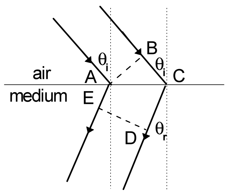
1.(1) According to the property described above, assuming that a light beam strikes from air on the surface of such an unusual material with relative permittivity and relative permeability , prove that the direction of the refracted light beam depicted in Fig.2-1 is reasonable. [1,2 т.]
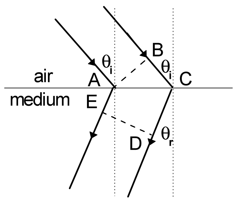
1.(2) For Fig. 2-1, show the relationship between refraction angle (the angle that refracted beam makes with the normal of the interface between air and the material) and incidence angle . [0,8 т.]
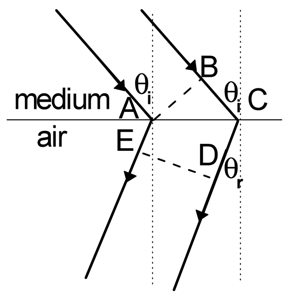
1.(3) Assuming that a light beam strikes from the unusual material on the interface between it and air, prove that the direction of the refracted light beam depicted in Fig.2-2 is reasonable. [1,2 т.]
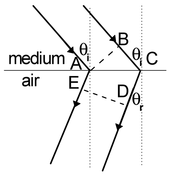
1.(4) For Fig. 2-2, show the relationship between the refraction angle (the angle that refracted beam makes with the normal of the interface between two media) and the incidence angle . [0,8 т.]
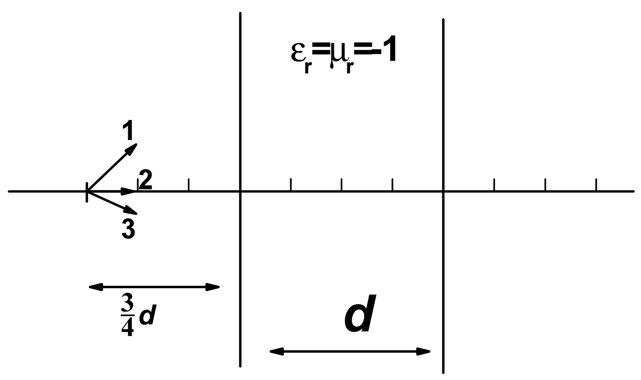
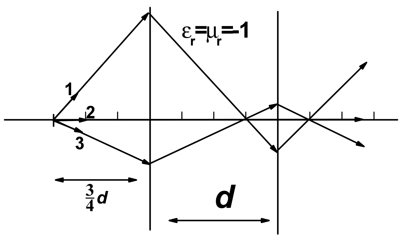
2. As shown in Fig. 2-3, a slab of thickness , which is made of an unusual optical material with , is placed in air, with a point light source located in front of the slab separated by a distance of . Accurately draw the ray diagrams for the three light rays radiated from the point source. (Hints: under the conditions given in this problem, no reflection would happen at the interface between air and the unusual material). [1 т.]
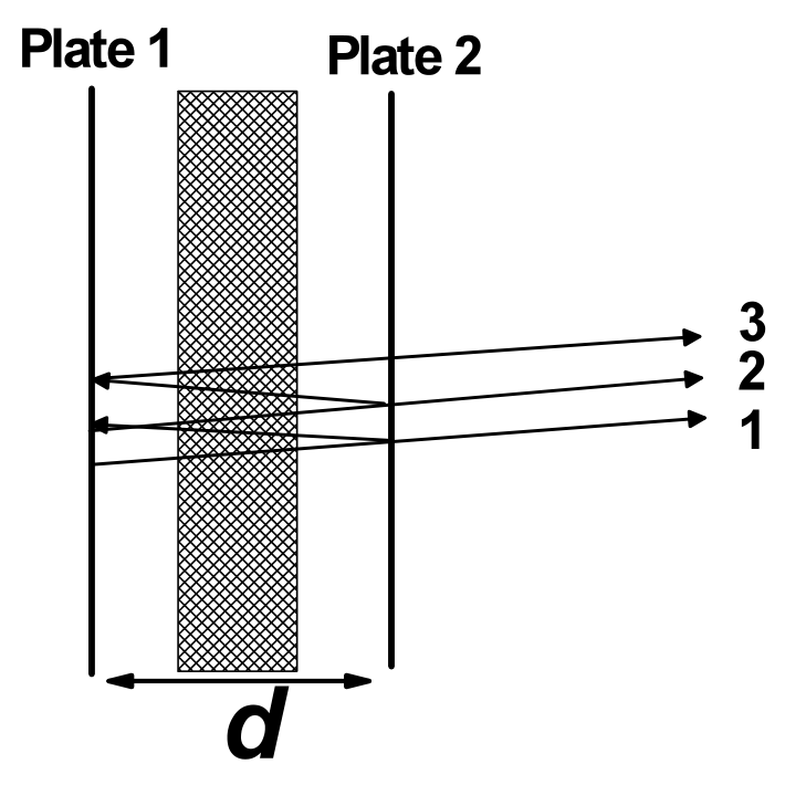
3. As shown in Fig. 2-4, a parallel-plate resonance cavity is formed by two plates parallel with each other and separated by a distant . Optically one of the plates, denoted as Plate 1 in Fig.2-4 , is ideally reflective (reflectance equals to 100%), and the other one, denoted by Plate 2, is partially reflective ( but with a high reflectance). Suppose plane light waves are radiated from a source located near Plate 1, then such light waves are multiply reflected by the two plates inside the cavity. Since optically the Plate 2 is not ideally reflective, some light waves will leak out of Plate 2 each time the light beam reaches it (ray 1, 2, 3, as shown in Fig. 2-4), while some light waves will be reflected by it. If these light waves are in-phase, they will interfere with each other constructively, leading to resonance. We assume that the light wave gains a phase of by reflection at either of the two plates. Now we insert a slab of thickness (shown as the shaded area in Fig. 2-4), made of an unusual optical material with , into the cavity parallel to the two plates. The remaining space is filled with air inside the cavity. Let us consider only the situation that the light wave travels along the direction perpendicular to the plates (the ray diagram depicted in Fig.2-4 is only a schematic one), calculate all the wavelengths that satisfy the resonance condition of such a cavity. (Hints: under the condition given here, no reflection would occur at the interfaces between air and the unusual material). [1 т.]
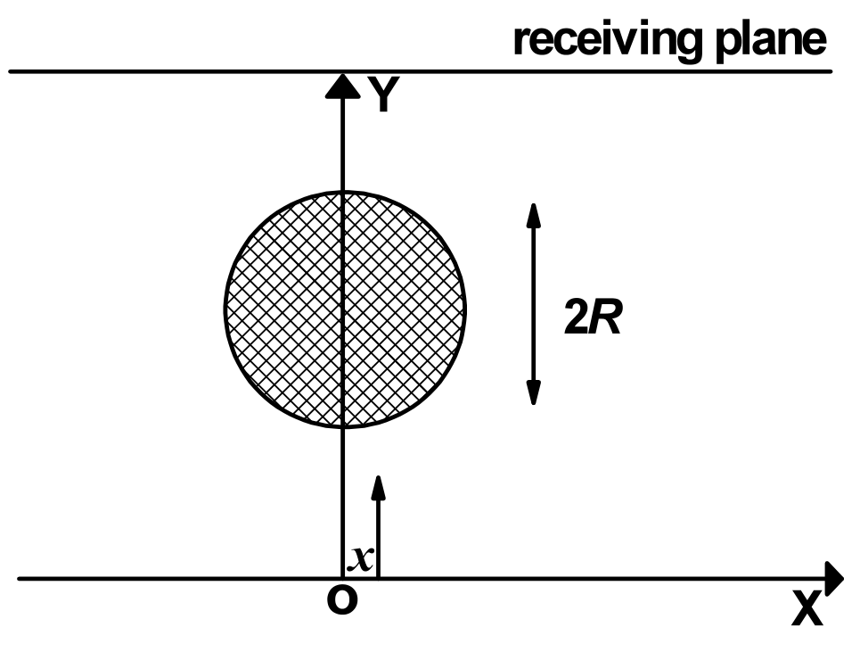
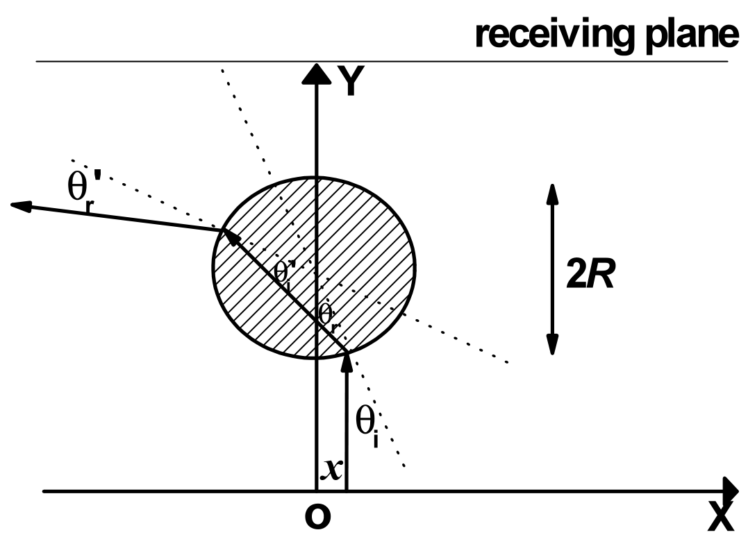
4. An infinitely long cylinder of radius , made of an unusual optical material with , is placed in air, its cross section in XOY plane is shown in Fig. 2-5 with the center located on Y axis. Suppose a laser source located on the X axis (the position of the source is described by its coordinate ) emits narrow laser light along the Y direction. Show the range of , for which the light signal emitted from the light source can not reach the infinite receiving plane on the other side of the cylinder. [1 т.]
Отговори
- 1.(2)
- 1.(4)
- 3.
- 4.
Решение
1. (1)
Prove: Assume E-D shows one of the wavefronts of the refracted light. According to the Huygens’ principle the phase accumulation from A to E should be equal to that from B via C to D:
With the Hints given these phase differences can be calculated respectively, then
Simplification of (2A.2) gives
Because and , we obtain
Therefore the schematic ray diagram of the refracted light shown in above figure is reasonable.
(2) From the above figure, the refraction angle and incidence angle satisfy
respectively. Substitution of (2A.5) into (2A.3) results in:
(3)
Prove: Assume E-D shows one of the wavefronts of refracted light.
According to the Huygens’ principle the phase accumulation from A to E should be equal to that from B via C to D:
With the Hints given these phase differences can be calculated respectively, then
Simplification of (2A.8) gives
Because and , we obtain
Therefore the schematic ray diagram of the refracted light shown in the above figure is reasonable.
(4) From the above figure, the refraction angle and incidence angle satisfy
respectively. Substitution of (2A.11) into (2A.9) results in :
2. The ray diagram is shown below.
Illustration:
The light is negatively refracted at both interfaces, and the refraction angle equals to incidence angle. Meanwhile according to the Hints provided there is no reflected light from each interface. Therefore within the medium light rays converge strictly at a point symmetric to the source about the left side of the medium, and on the other side of the medium the rays converge strictly at a point which is symmetric to the image of the source within the medium about the right side of the medium.
3. The phase difference between the two waves transmitting through the right side of the medium in succession is
On the right side of above equation the first term shows the phase difference of the light wave accumulated during its propagation in air, the second term shows the phase difference of the light wave accumulated during its propagation in the unusual medium, while the third term accounts for the phase difference of the light wave accumulated due to the two reflections in succession from the interface between air and the medium. Taking , (2A.13) changes into
Resonant condition means
Thus
4.
From the given conditions the ray diagram can be accordingly constructed. Above figure shows schematically the ray diagram for .Because for the unusual medium , from the solution of the first question we have .Therefore the direction of the final out-going light deviates from that of the incident light by .Because the direction of the incident light is given in the y direction, only if the condition
is satisfied the light signal can not reach the receiving plane. Notice
and the similarity of the monotonicity of to that of in the range of , we find that (2A. 17) goes to
Further taking the symmetry about the y axis into consideration we obtain that if the following condition
is satisfied, the light emitted from a light source located on the x axis can not reach the receiving plane.