EuPhO 2018, Експеримент — Задача 2. Interference
Porous membrane · 6 т.
General remarks
Provide detailed sketches of all the setups you use. Estimate errors only in part A. Depending on your method, you might be able to complete the tasks without using all the given equipment.
Porous membrane
You are going to study a membrane of anodic aluminum oxide. The membrane is transparent; it has thickness and cylindrical channels of diameter as shown in figure. Your goal is to determine parameters , and porosity (the volume fraction of channels in the membrane). Assume the membrane to be optically homogeneous and please do not touch the surface of the membrane!
Условие
Equipment Optical bench; membrane (identical to the one in part A) on a support; laser, ; 2 polarizers (axis of polarizer is marked with a line and forms with the edge of the frame); photodiode (short-circuit current is proportional to the light intensity); multimeter; wires; clips; 2 rulers; glue pads; white paper.
The reflection intensity depends on the angle of incidence due to interference of rays reflected from top and bottom surfaces of the membrane.
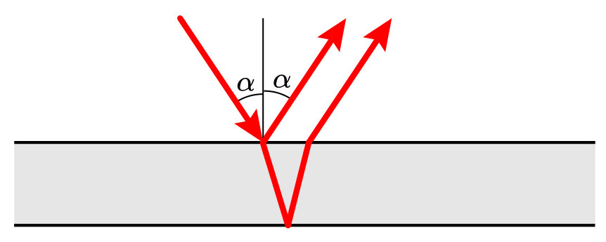
Task Determine the thickness of the membrane. Assume the refractive index of the membrane to be . To avoid birefringence described in part C incident light should have polarization perpendicular to the plane of incidence (plane of the figure). If the contrast of interference is too weak, try the other surface of the membrane.
Отговори
74.6 μm
Official reference value h = 74.6 ± 0.2 μm.
Решение
Optical path difference between beams reflected from top and bottom sides of the membrane:
appears because of phase change in case of reflection from the surface with higher refractive index.
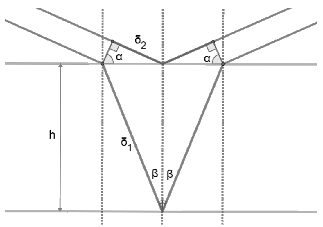
(1)
Reflectance maximums can be observed if , where is integer. Reflectance maximums can be observed if .
Rotating the sample, we can see dozens of minimums and maximums. depending on the number of minimum is linear according to the equation (1), as shown on the graph. Slope is equal .
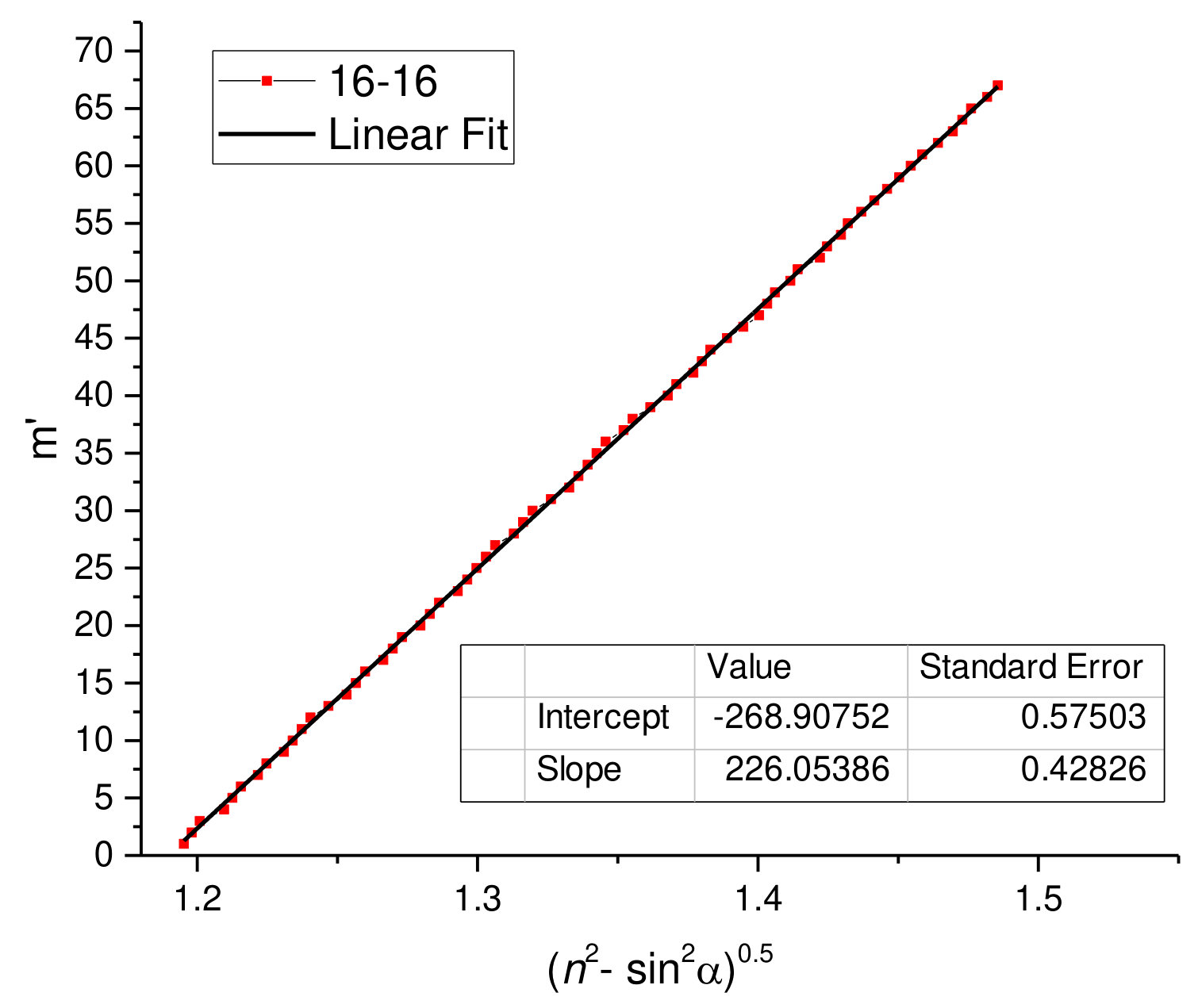
Slope and its uncertainty were calculated with OLS.
This data is shown for demonstration. During the competition, students were not supposed to measure positions of that much number of minimums and plot a graph, because this does not improve accuracy. The best solution is to rotate the sample and calculate number of minimums between two angles . The more is number of minimums , the better is accuracy. In this case, uncertainty may be estimated as .
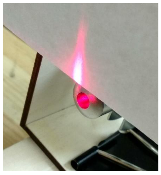
The sample is not fixed on the rotating table. Before the measurement, one should set a zero using the reflected laser beam.
Оригинал в Архива: exp_pr.pdf · официални решения: exp_sol.pdf