EuPhO 2018, Експеримент — Задача 3. Birefringence
Porous membrane · 7 т.
General remarks
Provide detailed sketches of all the setups you use. Estimate errors only in part A. Depending on your method, you might be able to complete the tasks without using all the given equipment.
Porous membrane
You are going to study a membrane of anodic aluminum oxide. The membrane is transparent; it has thickness and cylindrical channels of diameter as shown in figure. Your goal is to determine parameters , and porosity (the volume fraction of channels in the membrane). Assume the membrane to be optically homogeneous and please do not touch the surface of the membrane!
Условие
Equipment the same as in part B.
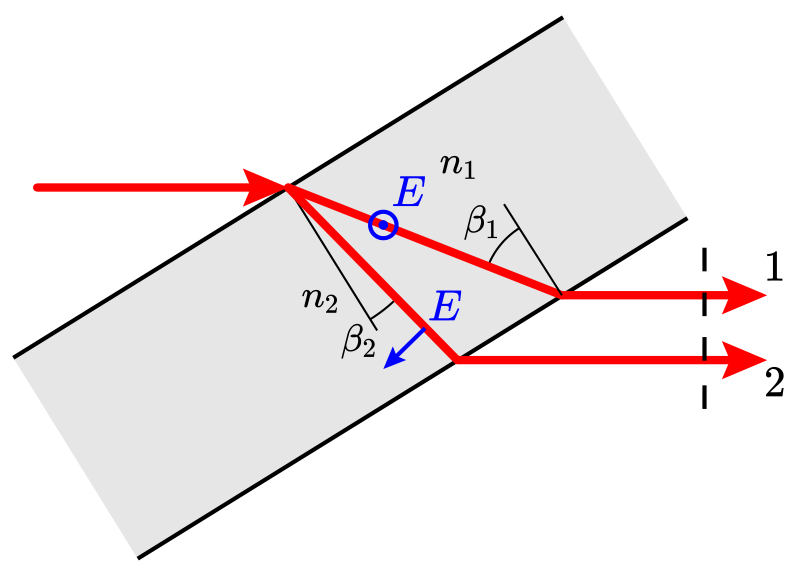
The refractive index of the membrane depends on polarization and propagation direction of light. The membrane can be described with two refractive indices: and ; . When laser beam enters membrane, it splits into two beams with different polarizations and velocities. Beam 1 is polarized normally to the plane of incidence; its refractive index and doesn't depend on . Beam 2 is polarized parallel to the plane of incidence; its refractive index depends on :
One can show that the optical path difference between the beams .
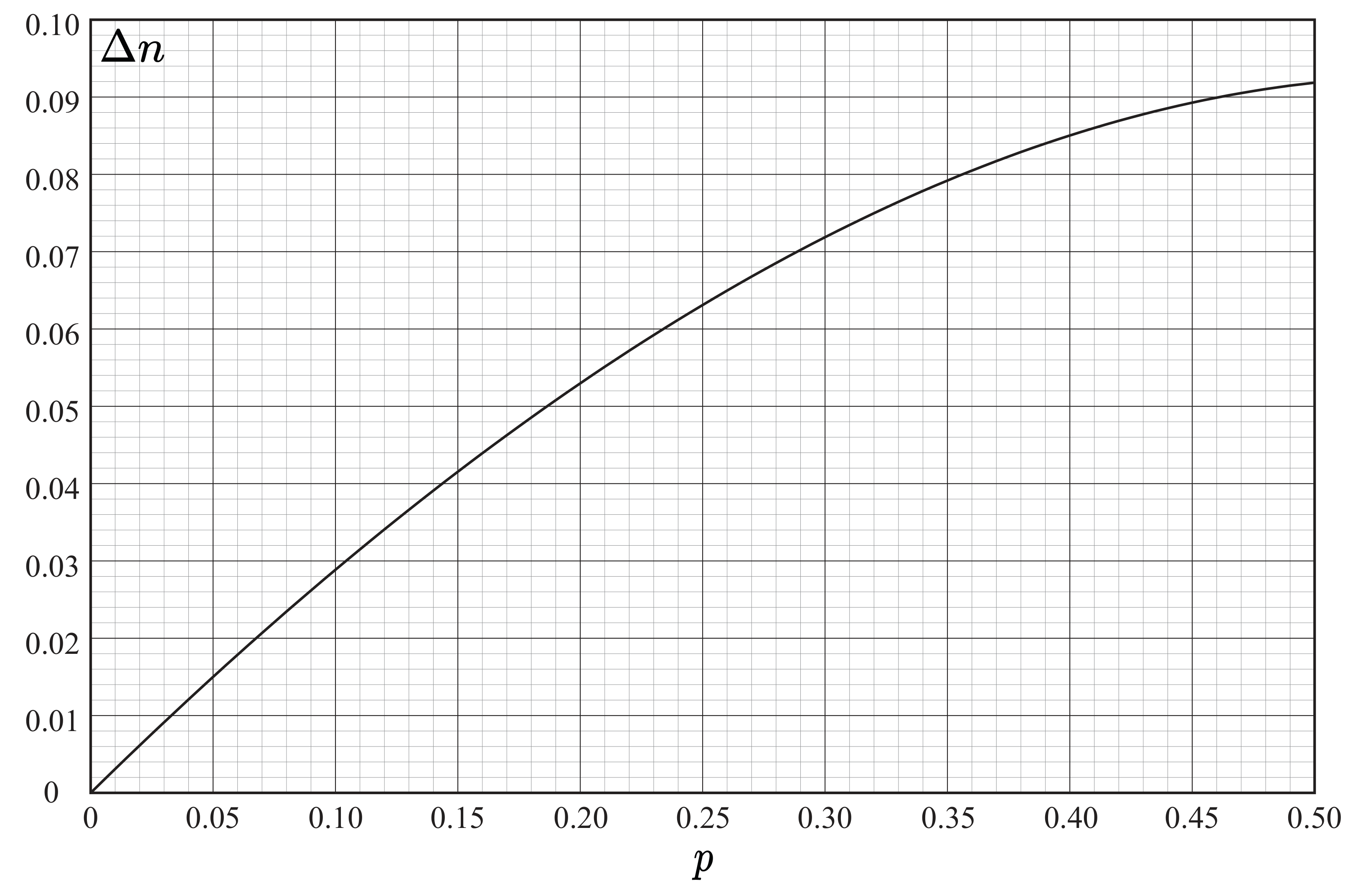
Task Determine the difference of the membrane. Find the porosity using the given plot of .
Отговори
Δn = 0.0378 ± 0.0015; p = 13.5 ± 0.5%
Official reference values.
Решение
In calculations me denote , .
From Snell's law
Optical path between beams is . Taking condition into account, we should derive in terms of and .
(C1)
Now we will derive in terms of .
(C2)
Combining (C1) and (C2), we obtain the equation:
(C3)
Relation between and may be found from formulae given in the task:
(C4)
(C5)
(C4)-(C5):
(C6)
Taking account of (C3), it yields:
(C7)
Polarized waves may interfere in projections. We should use 2 polarizers with polarization axes pointed at with membrane rotation axis.
First polarizer let beams 1 and 2 have equal intensity. Second polarizer projects waves on its polarization axis, so they can interfere. Polarization axes of polarizers may be perpendicular or parallel. Using the described setup, one can observe minimums with zero intensity and bright maximums.
Over setups me be used to observe the main effect. One can arrange the setup without second polarizer (laser beam is polarized itself), or place polarizers at angles differs from .
In any case, when we rotate the membrane, we can find three transmittance extrema. If we use the setup described above, optical paths in these points will be: , , .
Transmittance depending on the angle of incidence is shown on the graph. To obtain this perfect data, we also measured transmittance without the second polarizer to take account of reflectance rising at big angles.
Students were not supposed to take a lot of measurements or plot the graph, this isn't necessary to complete the task. To calculate with best possible accuracy, we just need to determine angles of three transmittance extrema by any way.
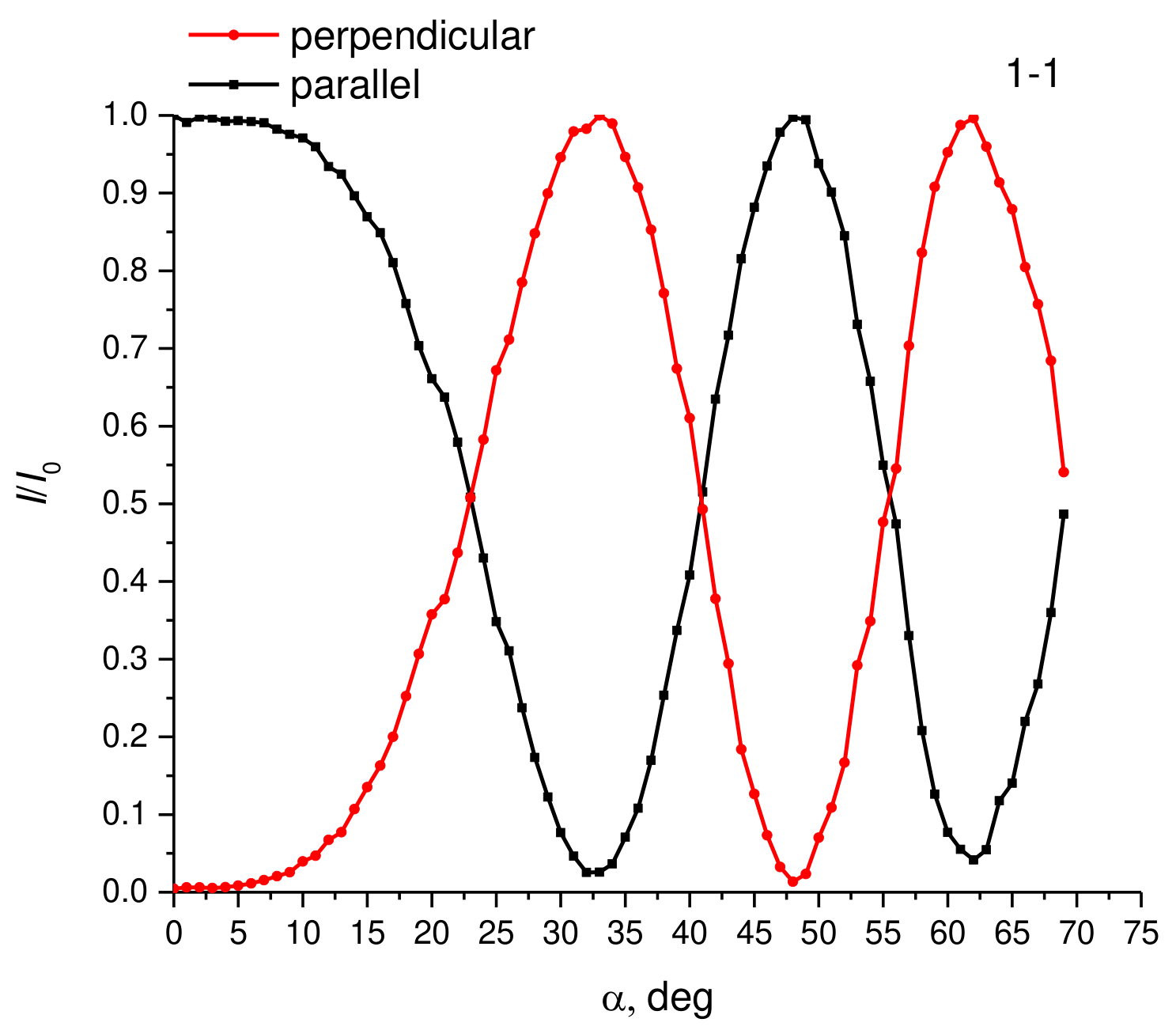
values are calculated according to the equation (C7).
| 32.5 | 20.1 | 0.0352 | |
| 48 | 27.2 | 0.0375 | |
| 62 | 31.8 | 0.0405 |
Using the plot , we determine the porosity of the sample.
Оригинал в Архива: exp_pr.pdf · официални решения: exp_sol.pdf