EuPhO 2023, Теория — Задача 3. T3: Plate between magnets
7. EuPhO 23 Hannover Germany. Theoretical Problems. Language: English · 10 т.
Условие
Two identical long, cylindrical rod magnets of radius are close to each other and share the same vertical symmetry axis. The polarity of the two magnets is the same. As a result, the magnetic field in the air gap between the magnets is directed towards the direction (see figure) and uniform with flux density . The magnetic field outside the gap is zero. A horizontal large non-magnetic metal plate is placed in the air gap and moved with constant horizontal velocity in -direction. The thickness of the plate is , the resistivity of the metal is .
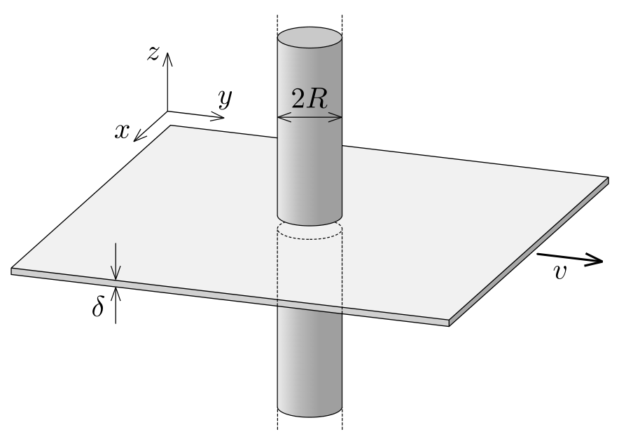
a) Sketch the shape of current streamlines in the metal plate at a given time. Indicate the axes on your sketch. [3 т.]
b) Find and plot the current density inside the plate along a line parallel to the axis intersecting the symmetry axis of the magnets. [5 т.]
c) Find the horizontal force required to move the plate. [2 т.]
Отговори
- b)
- c)
Решение
General remarks:
Calculational numerical errors - 0.2 p Dimensionally wrong answers - 0 p
Part a) (∼3 pts)
Let us analyze how the current in the metal starts to build up when we start moving the plate in the rest frame of the magnets. The free electrons in the metal try to move together with the plate in the direction, but a Lorentz force pointing in the direction makes them deviate.
After some time the charge accumulation stops and the charge and current distributions do not depend on time anymore. According to Ohm’s law,
where is the total current density, is the result of the Lorentz force, and is the current density caused by the electric field (and is therefore a potential field).
Inside the circular region () the Lorentz term is constant, but outside it is zero. Nevertheless, the -field of the accumulated charges is present there, which gives rise to a current. In the steady state considered here, the charge distribution is constant in time, and hence the total current density is source-free everywhere. However, this does not hold for which is driven by the ”sources” and ”sinks” along the rim of the circular region of radius . Those sources and sinks compensate exactly the sources of the Lorentz term mentioned above. Only a source-free jump of the total current density is allowed on the rim, resulting in the kinks on the streamlines along the boundary.
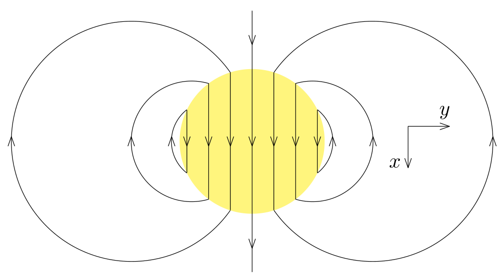
Based on these considerations, we can draw a qualitative pattern of the current flow: inside the circular disc, there is a flow in the direction of the Lorentz force and the streamlines of the created flow of current close onto themselves outside of that region as shown in the figure below.
| Grading scheme part a) | Pts |
|---|---|
| Streamlines are continuous and arrows are consistent along each streamline and streamlines don’t meet or intersect. If the streamlines are qualitatively (physically) wrong, 0 p should be given. | 1.0 |
| Twofold symmetry with respect to -axis (if axis is not indicated in any way, only 0.1 p) | 0.2 |
| Twofold symmetry with respect to -axis (if axis is not indicated in any way, only 0.1 p) | 0.2 |
| Indicating the boundary of the circular region | 0.1 |
| Breaking points on the boundary (only rewarded if both inside and outside streamlines are shown) | 0.8 |
| Along the -axis the direction of current density is inside and outside (if axis is not indicated in any way, 0.0 p; if the direction is correct in only one region, 0.3 p; if there is a sign mistake only, 0.3 p) | 0.7 |
| Stating that current density is homogeneous inside is not required in part a) | 0.0 |
| Total on part a) | 3.0 |
Part b (∼5 pts)
From here on, we make use of the uniqueness of the solution to the correctly posed boundary conditions for the Maxwell equations inside the plate. We need to satisfy the condition that current density is sourceless everywhere, i.e.
where denotes the current density and integral is taken over an arbitrary closed loop inside the plate. The current density must satisfy the Ohm’s law in differential form,
where denotes the velocity of the plate; the electric field caused by the accumulated charges must satisfy the circulation theorem,
where integration loop can be arbitrary. To close the system of equations we need to satisfy, we integrate Eq. 39 either over a closed loop entirely inside or entirely outside the circular region then we obtain zero, because for such loops . From this we conclude that for such integration loops,
Note that the electric field of a polarised cylinder satisfies Eq. 40, but we must also satisfy Eqns. (38,39). We will look for such a solution in the form of a superposition
First we need to find an expression for the field . To that end, we can consider the electric field produced by an infinite homogeneously charged cylinder of radius and volume charge density . From Gauss’s law, we can conclude that inside and outside the cylinder the electric field is
Now we can take another similar cylinder of charge density , displaced from the first cylinder by a small displacement vector . With the origin still at the centre of the positively charged cylinder, the electric field of this negatively charged cylinder is written as (which works for both inside and outside). Note that in the overlapping area of the two cylinders, the charge density is zero.
We consider the limit while keeping the product constant, which represents the volume density of the dipole moments (i.e. the polarisation), constant. In this case, the field inside can be calculated as
which is homogeneous.
Outside, the field is given by
Expanding the second term in the bracket up to first order ():
Substituting this into the formula of and simplifying:
This is the field of an ideal two-dimensional electric dipole. From this general formula we can obtain an expression for the field along the axis:
The normal component of this field exhibits discontinuity at the boundary of the cylinder given by the surface charge density , which can be found again from the superposition of the two cylinders: the non-overlapping region has the shape of a crescent moon of width in the direction; this means that the width in the radial direction is , where denotes the angle between the radius vector and the . Hence, we can find the surface charge density as . Due to Gauss’ law, the radial electric field jumps by an amount given by the surface charge density, . This corresponds to a jump in the magnitude of the current density
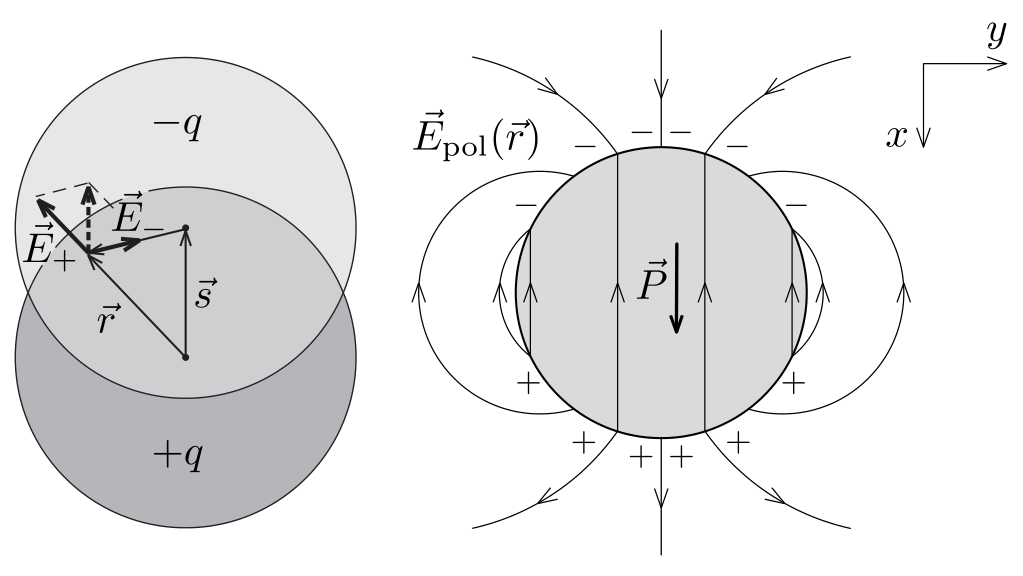
which must eliminate the discontinuity due to the jump in the radial component of the Lorentz force term in Eq. (42, equal to
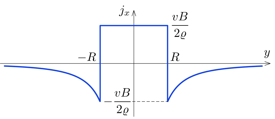
The cancellation occurs when . Putting all the results together, we can conclude that inside the cylinder, the current density in the plate is homogeneous and equal to
Outside the cylinder, along the axis, so that
Now we can plot the graph:
| Grading scheme part b) | Pts |
|---|---|
| Realizing that is driven by the sum of the term and the electric field (if only one term is considered, 0 p) | 0.5 |
| Writing the boundary condition for and for (or equivalent) | 0.5 |
| Guessing the solution of the 2D boundary value problem (either with analogy of a polarized dielectric cylinder or with the superposition of a 2D dipole field outside and a uniform field inside) | 1.0 |
| Calculating the electric field of a 2D dipole along the symmetry axis | 1.0 |
| Finding the appropriate weight of the dipole field (i.e. dipole moment) by matching boundary conditions | 0.5 |
| Expressing inside and outside correctly | 0.5 |
| Plotting the graph (axis are labelled correctly, 0.1+0.1; sign changes at the rim and function jumps, 0.3, function is constant in region 0.2, if the area below the curve could add up to zero 0.3) | 1.0 |
| Total on part b) | 5.0 |
Part c(∼2 pts)
Method 1: integrating the force density. Only the current inside the magnetic field contributes to the force. The force acting on an infinitesimal volume element of the metal slab is given by
Since and are uniform in the region of non zero , and perpendicular, the integral simplifies to
Using our previous result for the current density we get
The direction of the force is opposite to the velocity of the plate, in agreement with physical intuition.
| Grading of part c) - Method 1 | Pts |
|---|---|
| Expressing the force acting on a current element | 0.5 |
| integrating over the circular region | 1.0 |
| final result (it can be given only if prefactor is correct) | 0.5 |
| Total on part c) | 2.0 |
Method 2: integrating the dissipated power.
Due to energy conservation, the mechanical power provided by the external force is dissipated in the plate in the form of Joule heat:
The volume density of the dissipated power is , so the total power of dissipation can be written as an integral over the volume:
The first integral simplifies due to the constant current density inside the circular region of radius :
In order to evaluate the second integral, let us calculate first:
where the absolute value squared can be simplified as
so the quantity depends on the distance only (and not on the polar angle):
Now the power dissipated outside the circular region () can be written as:
Let us evaluate the integral:
It is an interesting coincidence that the power dissipated inside and outside is the same. Now the total power of dissipation is known and the force can be calculated:
| Grading of part c) - Method 2 | Pts |
|---|---|
| Expressing the force in terms of the dissipated power | 0.5 |
| integrating over the circular region | 0.3 |
| integrating over the outer region | 0.7 |
| final result (it can be given only if prefactor is correct) | 0.5 |
| Total on part c) | 2.0 |
An incorrect method of obtaining the correct answer. The correct solution described above can be carried out with minor modifications when using the reference frame of the plate, where the circular region of the magnetic field moves with velocity . The only difference is that the Lorentz force acting on the charge carriers in the cylinder frame is now replaced by the Coulomb force , where is the electric field resulting now from the Lorentz transformation.
What we need to notice is that there is no electric field outside of the cylinder () at large distances in the direction from the plate. Indeed, there are clearly no fields there (neither nor ) in the cylinder’s frame. Using the Lorentz transformation it is clear that no fields can emerge in our new frame. Meanwhile, outside the cylinder and inside the plate, there is definitely an electric field driving the current flow as derived above. The tangential-to-the-plate electric field cannot be discontinuous at the surface because the electrostatic field (in the cylinder’s frame) is potential. Hence, outside the cylinder and outside the plate, there is also an electric field in the neighbourhood of the plate, It is caused by the charge density formed on and in the plate, the generation of which is described in the solution of Part a). From large distances, however, these charges are seen as an electric dipole, whose field vanishes inversely proportional to the cubed distance.
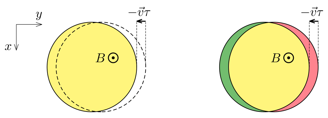
A tempting but incorrect approach is trying to describe the motion of the cylinder in the plate’s frame as a discontinuous stepping motion of the cylinders: at the current position of the cylinder, the magnetic flux disappears and at the same time reappears at a small distance away from its previous position. According to the Faradey’s law, the disappearing flux will produce circular clockwise fieldlines of , and the reappearing flux will produce slightly displaced counterclockwise fieldlines. The corresponding fields and their superposition can be easily calculated, see below. The result turns out to be exactly the same as the field obtained above for the field inside the plate. However, the equivalence of these fields is just a coincidence (there is a good reason for this coincidence: in both cases, the field is obtained as a superposition of the fields produced by two overlapping cylinders). Furthermore, there is a fundamental difference: in reality, the field is only observed in the plate (at ) and disappears at ; meanwhile, in the stepping cylinder model, the field remains the same regardless of the value of .
The reason why the stepping cylinder model gives an incorrect result — producing an electric field in those places where there clearly is none — lies in the theory of relativity. A continuously moving (not stepping) cylinder obtains a surface charge, because the current density and the charge density together form a 4-vector. There is a bound surface current on the surface of the cylinder (creating the magnetic field inside), and as the cylinder moves, the Lorentz transformation tells us that there will now also be a surface charge creating an electric field both inside and outside the cylinder. So, with a moving cylinder, the changing flux creates an electric field outside which is cancelled out by the surface charges on the cylinder. Inside the cylinder, these two fields add up constructively.
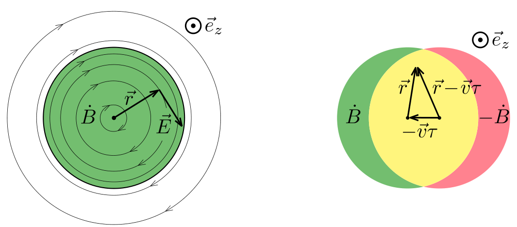
In what follows, we analyse mathematically the model of stepping cylinders. By considering two almost overlapping circles with a short time interval between, it is clear that any flux change occurs on rim (see fig. 1). This changing flux gives rise to an induced electric field which makes the charge carriers move inside the plate resulting electrical currents.
Considering the red region in the figure as the initial non-zero field, and the green region as the non-zero field after time , the yellow overlapping region corresponds to a non changing magnetic flux, while red on the right is decreasing, and green on the left is increasing. The average rate of change of -field in the two regions is , respectively.
The induced electric field can be found as a superposition of the electric fields generated by the flux change in the two overlapping circular regions. For one circular region with increasing -field in the direction, the magnitude of the electric field can be found from Faraday’s law applied for a circular -field line:
where the rate of enclosed flux change is given by
From here the modulus of the induced electric field can be expressed. It is convenient to write the result in the vectorial form with the help of position vector , unit vector and Lenz’s law:
A similar formula gives the -field generated by the region of decreasing magnetic flux, we only need to change the sign and replace with .
Now take the superposition of the induced electric fields produced by the two overlapping circular regions. Between the two magnets () we get
Using the differential form of Ohm’s law , we can conclude that the current density in the metal plate in the region is uniform,
where we used that .
Similarly, in the region we get:
Expanding the second term in the bracket up to first order ():
Substituting this into the formula of and simplifying:
Finally, the current density in the region is the following
| Grading of incorrect approach | Pts |
|---|---|
| part a) - same as the original marking scheme | 3.0 |
| If everything is done correctly - 2.0 p | 2.0 |
| part c) - same as the original marking scheme | 2.0 |
| Total for incorrect approach | 7.0 |
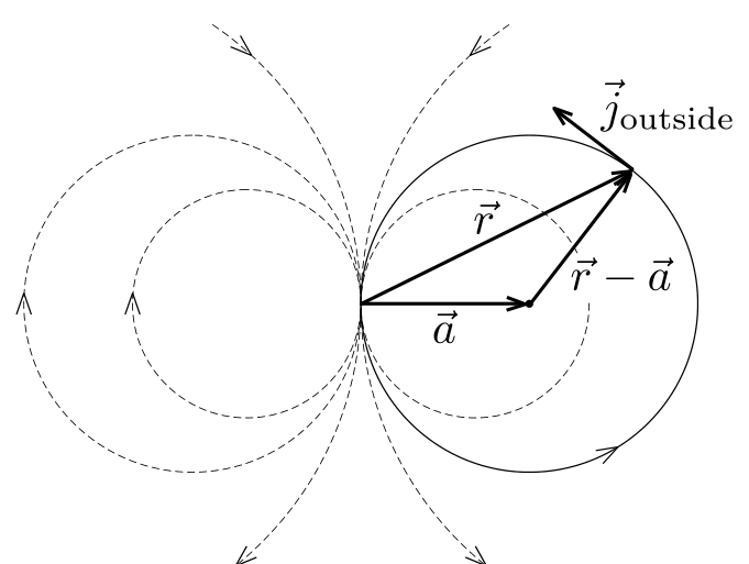
Note no. 1. Although it was not asked in the problem, it is fascinating that the streamlines in the region are circles. To prove this statement, take a circle of radius with center located at vector such that (see fig. 3). The position vectors of the points located on this circle satisfy the equation
Which can be rearranged in the form
We will show that is tangent to such a circle, regardless of the radius .
Consider the scalar product
Opening the brackets and using the equality we get:
which equals zero.
Note no. 2: The skin effect. Finally we need to discuss the applicability limits of the solution obtained above. We have assumed that at each point on the plate, the current density is constant across the entire -directional intersection of the plate. This requires the skin depth to be much greater than the thickness of the plate. The skin effect emerges due to the fact that for resistive media, the evolution of the magnetic field can be described by a diffusion equation
where the diffusivity . This means that for a very fast moving magnet, there is no time for the magnetic field to penetrate into the plate. Since any current is surrounded by a magnetic field according to Ampère’s circuital law, if there is no magnetic field, there can be no current, either. Consequently, the current will flow only in a narrow boundary layer of the plate. For a diffusive process, during a characteristic time , the penetration depth is estimated as . With estimated as , we get the condition
which is well satisfied for any metallic plates with reasonable orders of magnitude (e.g. , , ).
Оригинал в Архива: eupho2023_theory_problems.pdf · официални решения: eupho2023_theory_solutions.pdf