IPhO 1982, Теория и експеримент — Задача 1. Fluorescent lamp
Problems of the 13th International Physics Olympiad (Malente, 1982) · 10 т.
Abstract
The 13th International Physics Olympiad took place in 1982 in the Federal Republic of Germany. This article contains the competition problems, their solutions and a grading scheme.
Увод
In 1982 the Federal Republic of Germany was the first host of the Physics Olympiad outside the so-called Eastern bloc. The 13th International Physics Olympiad took place in Malente, Schleswig-Holstein. The competition was funded by the German Federal Ministry of Science and Education. The organisational guidelines were laid down by the work group “Olympiads for pupils” of the conference of ministers of education of the German federal states. The Institute for Science Education (IPN) at the University of Kiel was responsible for the realisation of the event. A commission of professors, whose chairman was appointed by the German Physical Society, were concerned with the formulation of the competition problems. All other members of the commission came from physics department of the university of Kiel or from the college of education at Kiel.
The problems as usual covered different fields of classical physics. In 1982 the pupils had to deal with three theoretical and two experimental problems, whereas at the previous Olympiads only one experimental task was given. However, it seemed to be reasonable to put more stress on experimental work. The degree of difficulty was well balanced. One of the theoretical problems could be considered as quite simple (problem 3: “hot-air balloon”). Another theoretical problem (problem 1: “fluorescent lamp”) had a mean degree of difficulty and the distribution of the points was a normal distribution with only a few excellent and only a few unsatisfying solutions. The third problem (problem 2: “oscillation coat hanger”) turned out to be the most difficult problem. This problem was generally considered as quite interesting because different ways of solving were possible. About one third of the pupils did not find an adequate start to the problem, but nearly one third of the pupils was able to solve the substantial part of the problem. That means, this problem polarized between the pupils. The two experimental tasks were quite different in respect of the input for the experimental setup and the time required for dealing with the problems, whereas they were quite similar in the degree of difficulty. Both required demandingly theoretical considerations and experimental skills. Both experimental problems turned out to be rather difficult. The tasks were composed in a way that on the one hand almost every pupil had the possibility to come to certain partial results and that there were some difficulties on the other hand which could only be solved by very few pupils. The difficulty in the second experimental problem (problem5: “motion of a rolling cylinder”) was the explanation of the experimental results, which were initially quite surprising. The difficulty in the other task (problem 4: “lens experiment") was the revealing of an observation method with a high accuracy (parallax). The five hours provided for solving the two experimental problems were slightly too short. According to that, in both experiments only a few pupils came up with excellent solutions. In problem 5 nobody got the full points.
The problems presented here are based on the original German and English versions of the competition problems. The solutions are complete but in some parts condensed to the essentials. Almost all of the original hand-made figures are published here.
Contact: Leibniz-Institute for Science Education (IPN) at the University of Kiel, Olshausenstrasse 62, 24098 Kiel, Germany, ipho@ipn.uni-kiel.de
Условие
An alternating voltage of 50 Hz frequency is applied to the fluorescent lamp shown in the accompanying circuit diagram.
The following quantities are measured:
overall voltage (main voltage)
electric current
partial voltage across the fluorescent lamp
ohmic resistance of the series reactor
The fluorescent lamp itself may be considered as an ohmic resistor in the calculations.
a) What is the inductance of the series reactor? [2 т.]
b) What is the phase shift between voltage and current? [1 т.]
c) What is the active power transformed by the apparatus? [1 т.]
d) Apart from limiting the current the series reactor has another important function. Name and explain this function!
Hint: The starter includes a contact which closes shortly after switching on the lamp, opens up again and stays open. [1 т.]
e) In a diagram with a quantitative time scale sketch the time sequence of the luminous flux emitted by the lamp. [1 т.]
f) Why has the lamp to be ignited only once although the applied alternating voltage goes through zero in regular intervals? [1 т.]
g) According to the statement of the manufacturer, for a fluorescent lamp of the described type a capacitor of about can be switched in series with the series reactor. How does this affect the operation of the lamp and to what intent is this possibility provided for? [2 т.]
h) Examine both halves of the displayed demonstrator lamp with the added spectroscope. Explain the differences between the two spectra. You may walk up to the lamp and you may keep the spectroscope as a souvenir. [1 т.]
Отговори
a) 1.09 H
b) 64.1 °
c) 59.88 W
The official solution gives 59.88 W (via U·I·cos φ) and 59.87 W (via R·I²).
Решение
a) The total resistance of the apparatus is ,
the ohmic resistance of the tube is .
Hence the total ohmic resistance is .
Therefore the inductance of the series reactor is: .
This yields .
b) The impedance angle is obtained from .
Thus .
c) The active power can be calculated in different ways:
d) By opening the contact in the starter a high induction voltage is produced across the series reactor (provided the contact does not open exactly the same moment, when the current goes through zero). This voltage is sufficient to ignite the lamp. The main voltage itself, however, is smaller than the ignition voltage of the fluorescent tube.
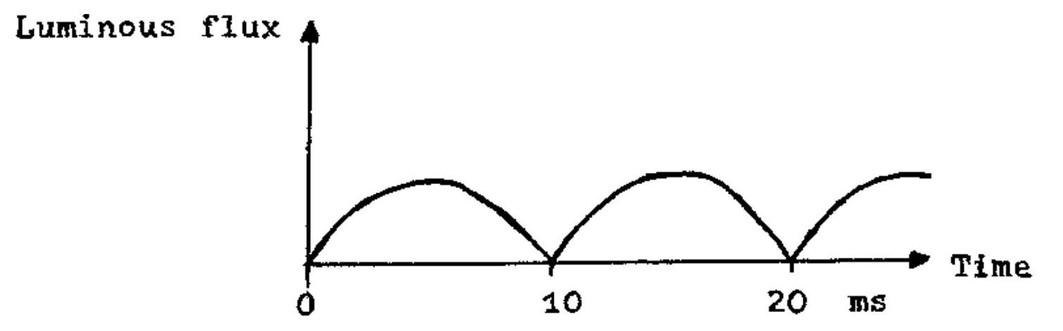
e) (figure)
f) The recombination time of the ions and electrons in the gaseous discharge is sufficiently large.
g) The capacitive resistance of a capacitor of is
The two reactances subtract and there remains a reactance of acting as a capacitor.
The total resistance of the arrangement is now
which is very close to the total resistance without capacitor, if you assume the capacitor to be loss-free (cf. a) ). Thus the lamp has the same operating qualities, ignites the same way, and a difference is found only in the impedance angle , which is opposite to the angle calculated in b):
Such additional capacitors are used for compensation of reactive currents in buildings with a high number of fluorescent lamps, frequently they are prescribed by the electricity supply companies. That is, a high portion of reactive current is unwelcome, because the power generators have to be layed out much bigger than would be really necessary and transport losses also have to be added which are not payed for by the customer, if pure active current meters are used.
h) The uncoated part of the demonstrator lamp reveals the line spectrum of mercury, the coated part shows the same line spectrum over a continuous background. The continuous spectrum results from the ultraviolet part of the mercury light, which is absorbed by the fluorescence and re-emitted with smaller frequency (energy loss of the photons) or larger wavelength respectively.
Grading schemes
| Problem 1: Fluorescent lamp | pts. |
|---|---|
| Part a | 2 |
| Part b | 1 |
| Part c | 1 |
| Part d | 1 |
| Part e | 1 |
| Part f | 1 |
| Part g | 2 |
| Part h | 1 |
| 10 |
Оригинал в Архива: ipho82.pdf