IPhO 1985, Теория и експеримент — Задача 2. Problem 2
Problems and solutions of the 16th IPhO Portorož, Slovenia, (Former Yugoslavia), 1985 · 10 т.
Условие
In a long bar having the shape of a rectangular parallelepiped with sides , , and (), made from the semiconductor InSb flows a current parallel to the edge . The bar is in an external magnetic field which is parallel to the edge . The magnetic field produced by the current can be neglected. The current carriers are electrons. The average velocity of electrons in a semiconductor in the presence of an electric field only is , where is called mobility. If the magnetic field is also present, the electric field is no longer parallel to the current. This phenomenon is known as the Hall effect.
a) Determine what the magnitude and the direction of the electric field in the bar is, to yield the current described above.
b) Calculate the difference of the electric potential between the opposite points on the surfaces of the bar in the direction of the edge .
c) Find the analytic expression for the DC component of the electric potential difference in case b) if the current and the magnetic field are alternating (AC); and .
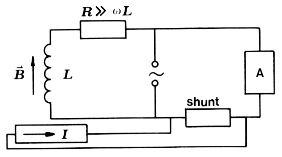
d) Design and explain an electric circuit which would make possible, by exploiting the result c), to measure the power consumption of an electric apparatus connected with the AC network.
Data: The electron mobility in InSb is , the electron concentration in InSb is , , , , , .
Отговори
a) 4.06 V/m
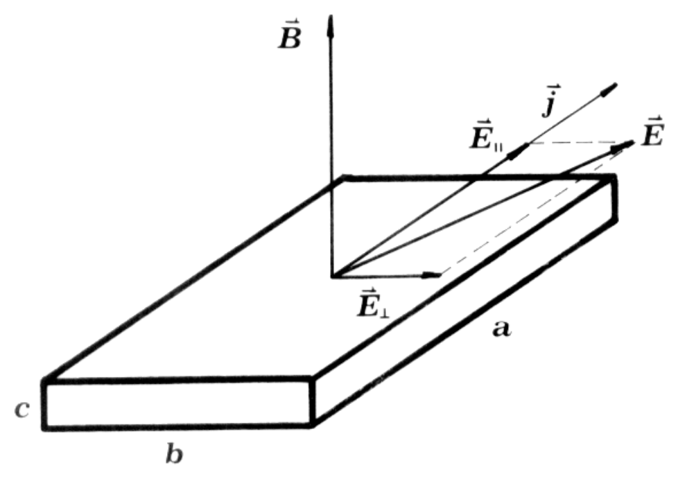
E∥ = 3.2 V/m along the current, E⊥ = 2.5 V/m in the direction b (Fig. 5).
b) 25 mV
c)
Решение
a) First the electron velocity is calculated from the current I:
The components of the electric field are obtained from the electron velocity. The component in the direction of the current is
(0.5p.)
The component of the electric field in the direction is equal to the Lorentz force on the electron divided by its charge:
(1p.)
The magnitude of the electric field is
(0.5p.)
while its direction is shown in Fig. 5 (Note that the electron velocity is in the opposite direction with respect to the current.) (1.5 p.)
b) The potential difference is
(1p.)
c) The potential difference is now time dependent:
The DC component of is
(3p.)
d) A possible experimental setup is-shown in Fig. 6
(2 p.)
Оригинал в Архива: ipho85.pdf