IPhO 1985, Теория и експеримент — Задача 5. Exercise B
Problems and solutions of the 16th IPhO Portorož, Slovenia, (Former Yugoslavia), 1985 · 10 т.
Условие
Locate the position of the centers and determine the orientations of a number of identical permanent magnets hidden in the black painted block. A diagram of one such magnet is given in Figure 1. The coordinates , and should be measured from the red corner point, as indicated in Figure 2.
Determine the component of the magnetic induction vector in the plane at by calibrating the measuring system beforehand.
Find the greatest magnetic induction obtainable from the magnet supplied.
Instrumentation
- Permanent magnet given is identical to the hidden magnets in the block.
- Induction coil; 1400 turns,
- Field generating coils, 8800 turns, , 2 pieces
- Black painted block with hidden magnets
- Voltmeter (ranges 1 V, 3 V and 10 V recommended)
- Electronic circuit (recommended supply voltage 24 V)
- Ammeter
- Variable resistor
- Variable stabilized power supply 0 – 25 V, with current limiter
- Four connecting wires
- Supporting plate with fixing holes
- Rubber bands, multipurpose (e. g. for coil fixing)
- Tooth picks
- Ruler
- Thread
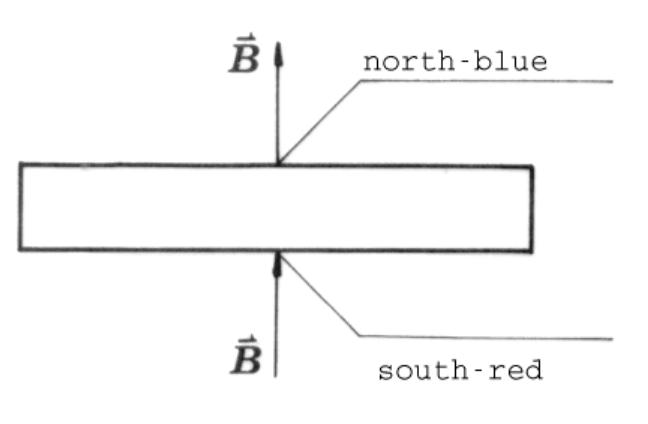
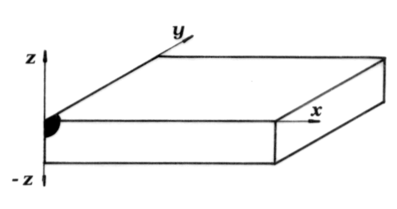
Instructions
For the magnet-search only nondestructive methods are acceptable. The final report should include results, formulae, graphs and diagrams. The diagrams should be used instead of comments on the methods used wherever possible.
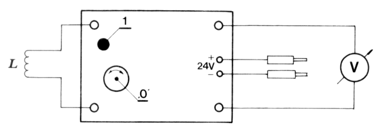
The proper use of the induced voltage measuring system is shown in Figure 3.
This device is capable of responding to the magnetic field. The peak voltage is proportional to the change of the magnetic flux through the coil.
The variable stabilized power supply is switched ON (1) or OFF (0) by the lower left pushbutton. By the (U) knob the output voltage is increased through the clockwise rotation. The recommended voltage is 24 V. Therefore switch the corresponding toggle switch to the 12 V – 25 V position. With this instrument either the output voltage or the output current is measured, with respect to the position of the corresponding toggle switch (V,A). However, to get the output voltage the upper right switch should be in the ’Vklop’ position. By the knob (I) the output current is limited bellow the preset value. When rotated clockwise the power supply can provide 1.5 A at most.
Note: permeability of empty space .
Отговори
0.21 T
Greatest value of B obtainable from the magnet, from the official solution; the calibration gave B/U = 0.020 T/V.
Решение
Two permanent magnets having the shape of rectangular parallelepipeds with sides 50 mm, 20 mm and 8 mm are hidden in a block of polystyrene foam with dimension 50 cm, 31 cm and 4.0 cm. Their sides are parallel to the sides of the block. One of the hidden magnets (A) is positioned so that its (Fig. 15) points in direction and the other (B) with its in or direction (Fig. 15).
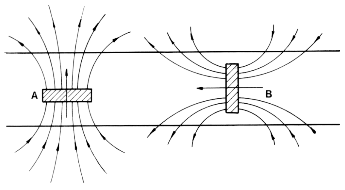
The positions and the orientations of the magnets should be determined on the basis of observations of forces acting on the extra magnet. The best way to do this is to hang the extra magnet on the thread and move it above the surface to be explored. Three areas of strong forces are revealed when the extra magnet is in the horizontal position i. e. its is parallel to axis, suggesting that three magnets are hidden. Two of these areas producing an attractive force in position P (Fig. 16) and a repulsive force in position R are closely together.
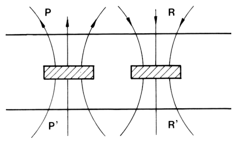
However, by inspecting the situation on the other side of the block, again an attractive force in area P’ is found, and a repulsive one in area R’. This is in the contradiction with the supposed magnets layout in Fig. 16 but corresponds to the force distribution of magnet B in Fig. 15.
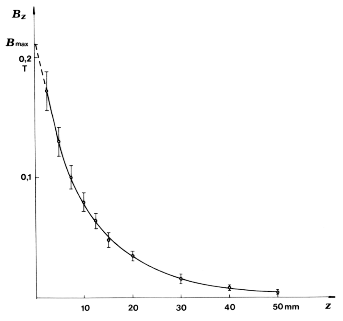
To determine the position of the hidden magnets one has to measure the component of on the surface of the block and compare it to the measurement of of the extra magnet as a function of distance from its center (Fig. 18). To achieve this the induction coil of the measuring system is removed from the point in which the magnetic field is measured to a distance in which the magnetic field is practically zero, and the peak voltage is measured.
In order to make the absolute calibration of the measuring system, the response of the system to the known magnetic field should be measured. The best defined magnetic field is produced in the gap between two field generating coils. The experimental layout is displayed in Fig. 17.
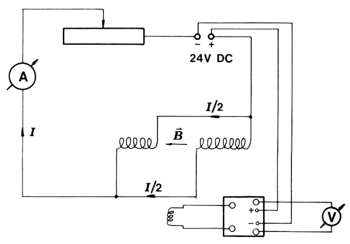
The magnetic induction in the gap between the field generating coils is calculated using the formula:
Here is the number of the turns of one of the coils, its length , the width of the gap, and the current through the ammeter. The peak voltage, , is measured when the induction coil is removed from the gap.
Plotting the magnetic induction as a function of peak voltage, we can determine the sensitivity of our measuring system:
(More precise calculation of the magnetic field in the gap, which is beyond the scope of the exercise, shows that the true value is only 60 % of the value calculated above.)
The greatest value of is 0.21 T.
Marking scheme:
a) determination of position of magnets (±1 cm) 1 p.
b) determination of the orientations 1 p.
c) depth of magnets (±4 mm) 2 p.
d) calibration (±50 %) 3 p.
e) mapping of the magnetic field 2 p.
f) determination of (±50 %) 1 p.
Оригинал в Архива: ipho85.pdf