IPhO 1985, Теория и експеримент — Задача 4. Exercise A
Problems and solutions of the 16th IPhO Portorož, Slovenia, (Former Yugoslavia), 1985 · 10 т.
Условие
Follow the acceleration and the deceleration of a brass disk, driven by an AC electric motor. From the measured times of half turns, plot the angle, angular velocity and angular acceleration of the disk as functions of time. Determine the torque and power of the motor as functions of angular velocity.
Instrumentation
- AC motor with switch and brass disk
- Induction sensor
- Multichannel stop-watch (computer)
Instruction
The induction sensor senses the iron pegs, mounted on the disk, when they are closer than 0.5 mm and sends a signal to the stop-watch. The stop-watch is programmed on a computer so that it registers the time at which the sensor senses the approaching peg and stores it in memory. You run the stop-watch by giving it simple numerical commands, i. e. pressing one of the following numbers:
5 – MEASURE.
The measurement does not start immediately. The stop-watch waits until you specify the number of measurements, that is, the number of successive detections of the pegs:
3 – 30 measurements
6 – 60 measurements
Either of these commands starts the measurement. When a measurement is completed, the computer displays the results in graphic form. The vertical axis represents the length of the interval between detection of the pegs and the horizontal axis is the number of the interval.
7 – display results in numeric form.
The first column is the number of times a peg has passed the detector, the second is the time elapsed from the beginning of the measurement and the third column is the length of the time interval between the detection of the two pegs.
In the case of 60 measurements:
8 – displays the first page of the table
2 – displays the second page of the table
4 – displays the results graphically.
A measurement can be interrupted before the prescribed number of measurements by pressing any key and giving the disk another half turn.
The motor runs on 25 V AC. You start it with a switch on the mounting base. It may sometimes be necessary to give the disk a light push or to tap the base plate to start the disk.
The total moment of inertia of all the rotating parts is: .
Решение
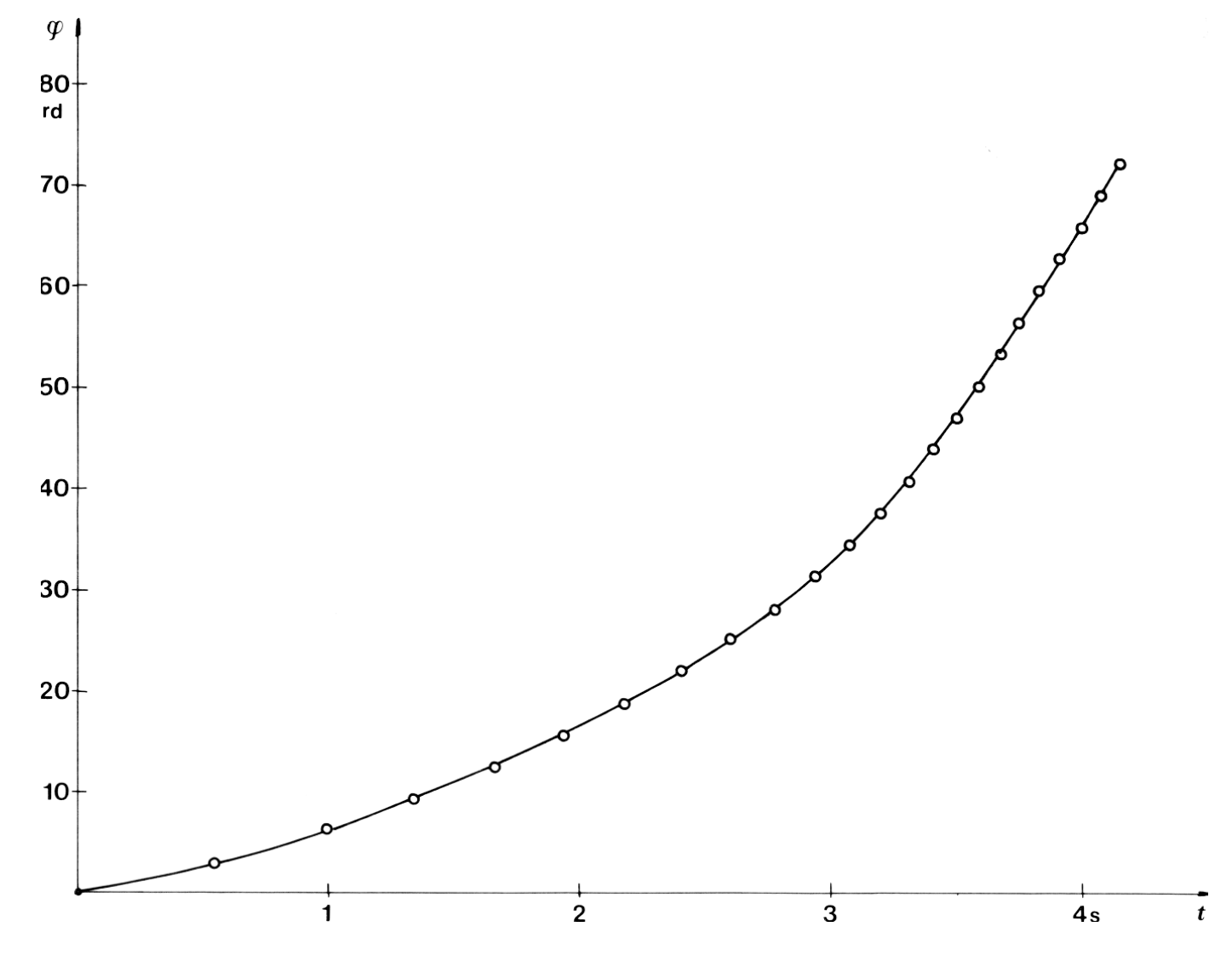
The plot of the angle as a function of time for a typical measurement of the acceleration of the disk is shown in Fig. 9.
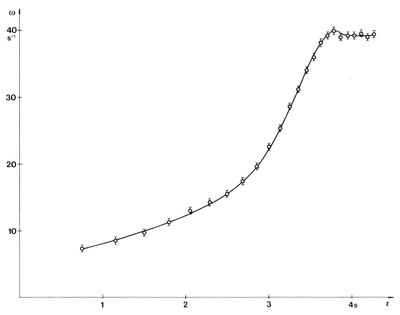
The angular velocity is calculated using the formula:
and corresponds to the time in the middle of the interval : . The calculated values are displayed in Table 1 and plotted in Fig. 10.
Observing the time intervals of half turns when the constant angular velocity is reached, one can conclude that the iron pegs are not positioned perfectly symmetrically. This systematic error can be neglected in the calculation of angular velocity, but not in the calculation of angular acceleration. To avoid this error we use the time intervals of full turns:
where ,
and .
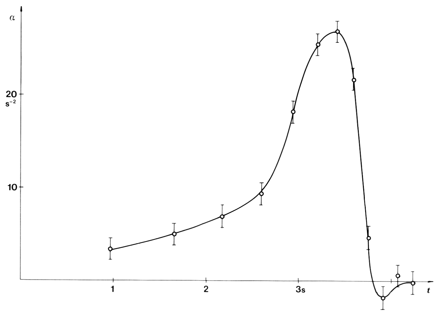
The angular acceleration as a function of time is plotted in Fig. 11.
The torque, , and the power, , necessary to drive the disk (net torque and net power), are calculated using the relation:
and
where the moment of inertia, , is given. The corresponding angular velocity is determined from the plot in Fig. 10 by interpolation. This plot is used also to find the torque and the power as functions of angular velocity (Fig. 12 and 13).
| ms | ms | rd | ms | s | s | |
| 1 | 0.0 | 0.0 | ||||
| 272.0 | 5.78 | |||||
| 2 | 543.9 | 543.9 | 3.14 | |||
| 758.7 | 7.31 | |||||
| 3 | 973.5 | 429.6 | 6.28 | 3.38 | ||
| 1156.3 | 8.60 | |||||
| 4 | 1339.0 | 365.5 | 9.42 | |||
| 1499.9 | 9.76 | |||||
| 5 | 1660.8 | 327.8 | 12.57 | 5.04 | ||
| 1798.6 | 11.40 | |||||
| 6 | 1936.3 | 275.5 | 15.71 | |||
| 2057.1 | 13.01 | |||||
| 7 | 2177.8 | 241.5 | 18.85 | 5.96 | ||
| 2287.2 | 14.36 | |||||
| 8 | 2396.6 | 218.8 | 21.99 | |||
| 2498.1 | 15.48 | |||||
| 9 | 2599.6 | 203.0 | 25.73 | 9.40 | ||
| 2689.6 | 17.46 | |||||
| 10 | 2779.5 | 179.9 | 28.27 | |||
| 2859.4 | 19.66 | |||||
| 11 | 2939.3 | 159.8 | 31.42 | 18.22 | ||
| 3008.6 | 22.65 | |||||
| 12 | 3078.0 | 138.7 | 34.56 | |||
| 3139.9 | 25.38 | |||||
| 13 | 3201.8 | 123.8 | 37.70 | 25.46 | ||
| 3256.6 | 28.66 | |||||
| 14 | 3311.4 | 109.6 | 40.84 | |||
| 3361.8 | 31.20 | |||||
| 15 | 3472.1 | 100.7 | 43.98 | 26.89 | ||
| 3458.2 | 34.11 | |||||
| 16 | 3504.2 | 92.1 | 47.12 | |||
| 3547.8 | 36.07 | |||||
| 17 | 3591.3 | 87.1 | 50.27 | 21.72 | ||
| 3632.4 | 38.27 | |||||
| 18 | 3673.4 | 82.1 | 53.41 | |||
| 3713.5 | 39.22 | |||||
| 19 | 3753.5 | 80.1 | 56.55 | 4.76 | ||
| 3792.8 | 39.97 | |||||
| 20 | 3832.7 | 78.6 | 59.69 | |||
| 3872.4 | 39.03 | |||||
| 21 | 3912.6 | 80.5 | 62.83 | −1.69 | ||
| 3952.7 | 39.22 | |||||
| 22 | 3992.7 | 80.1 | 65.97 | |||
| 4032.8 | 39.22 | |||||
| 23 | 4072.8 | 80.1 | 69.12 | 0.77 | ||
| 4112.4 | 39.67 | |||||
| 24 | 4152.0 | 79.2 | 72.26 | |||
| 4192.3 | 39.03 | |||||
| 25 | 4232.5 | 80.5 | 75.40 | −0.15 | ||
| 4272.4 | 39.42 | |||||
| 26 | 4312.3 | 79.7 | 78.54 |
Table 1
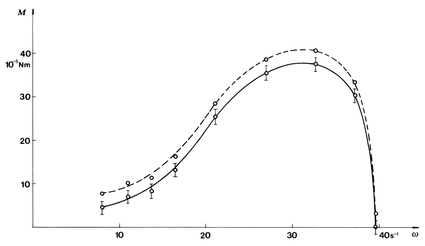
To find the total torque and the power of the motor, the torque and the power losses due to the friction forces have to be determined and added to the corresponding values of net torque and power. By measuring the angular velocity during the deceleration of the disk after the motor has been switched off (Fig. 14), we can determine the torque of friction which is approximately constant and is equal to .
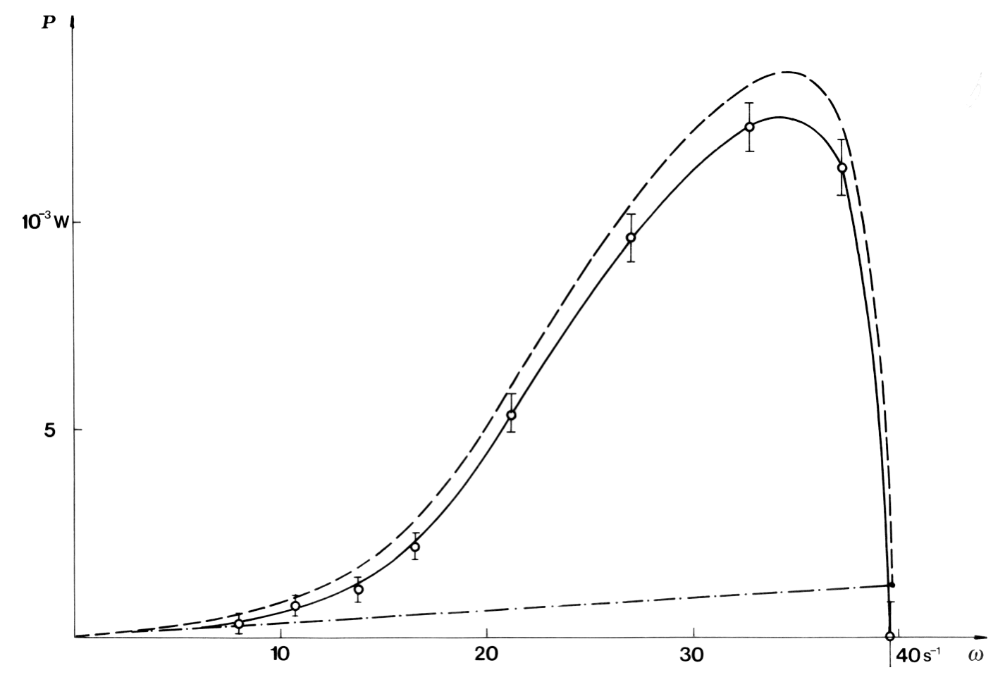
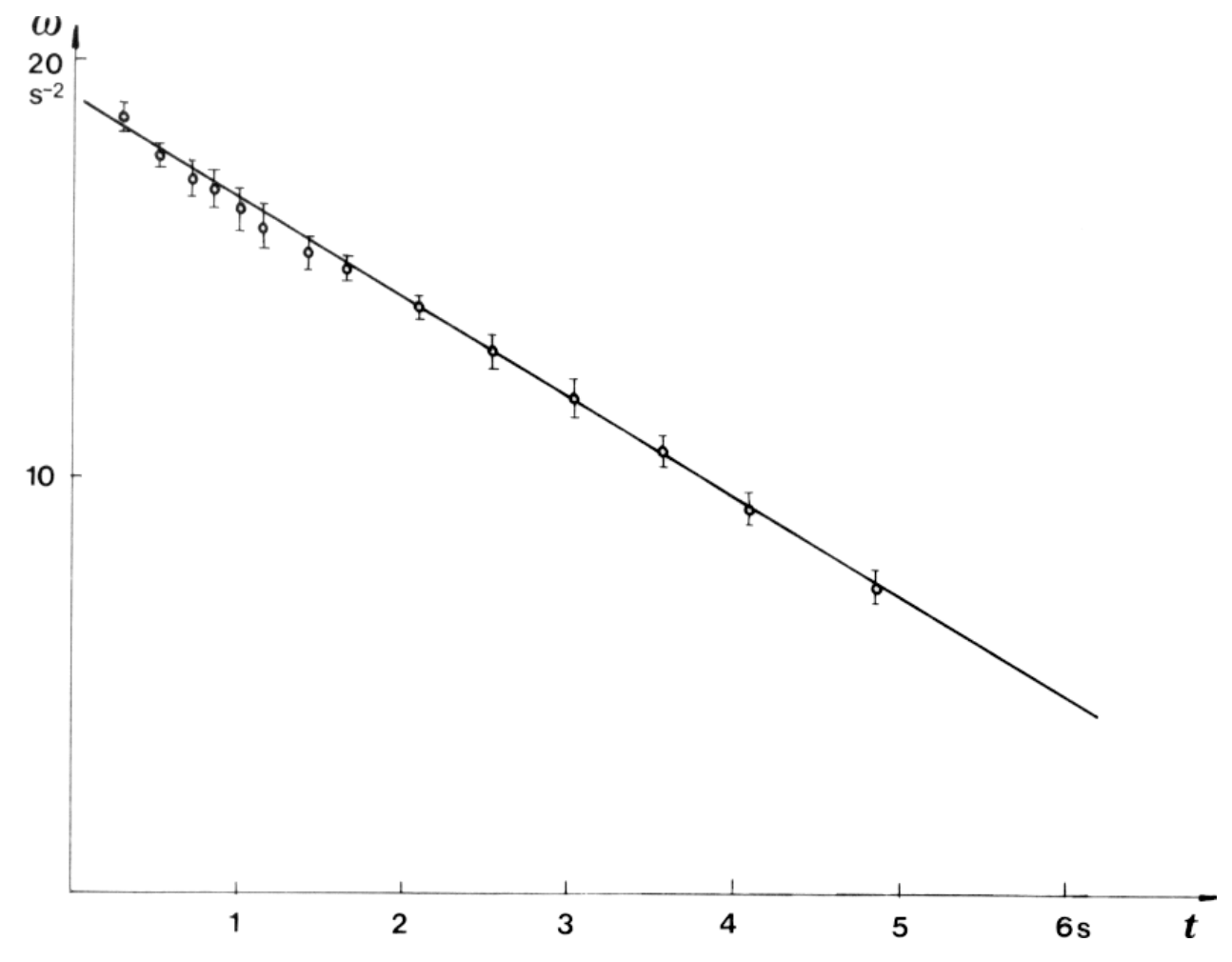
The total torque and the total power are shown in Fig. 12 and 13.
Marking scheme
a) Determination of errors 1 p.
b) Plot of angle vs. time 1 p.
c) Plot of angular velocity and acceleration 3 p.
d) Correct times for angular velocity 1 p.
e) Plot of net torque vs. angular velocity 2 p. (Plot of torque vs. time only, 1 p.)
f) Plot of net power vs. angular velocity 1 p.
g) Determination of friction 1 p.
Оригинал в Архива: ipho85.pdf