IPhO 1990, Теория и експеримент — Задача 5. Determination of the ratio of the magnetic field strengths of two different magnets.
THE 21st INTERNATIONAL PHYSICS OLYMPIAD - 1990 · 10 т.
Внимание: Бележка към темата
Complete combined archive booklet, attributed to Hans Jordens, contains three theory questions and two experiments with keys. Printed errors and gaps are preserved: the neutron-star key changes the flattening denominator and uses a square-law radius inference; the LED key references missing graphs, has printed inconsistent table values and one unassigned final value; magnet-speed tables print m/s but their values match cm/s. Native source values and all grading remain unchanged.
Условие
Introduction
When a conductor moves in a magnetic field, currents are induced: these are the so-called eddy currents. As a consequence of the interaction between the magnetic field and the induced currents, the moving conductor suffers a reactive force. Thus an aluminium disk that rotates in the neighbourhood of a stationary magnet experiences a braking force.
Material available
- A stand.
- A clamp.
- An homogenius aluminium disk on an axle, in a holder, that can rotate.
- Two magnets. The geometry of each is the same (up to 1%); each consists of a clip containing two small magnets of identical magnetization and area, the whole producing a homogenius field, or .
- Two weights. One weight has twice the mass (up to 1%) of the other.
- A stop-watch.
- A ruler.
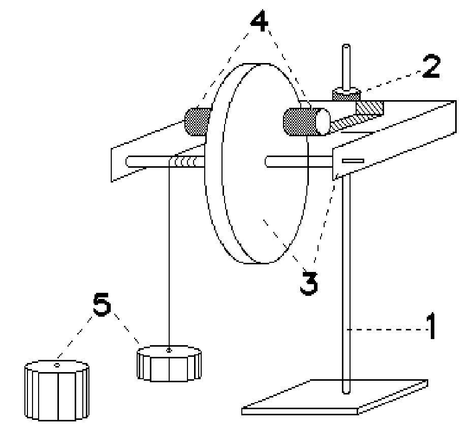
The experiment
The aluminium disk is fixed to an axle, around which a cord is wrapped. A weight hangs from the cord; and when the weight is released, the disk accelerates until a constant angular velocity is reached. The terminal speed depends, among other things, on the magnitude of the magnetic field strength of the magnet.
Two magnets of different field strengths or , are available. Either can be fitted on to the holder that carries the aluminium disk: they may be interchanged.
Instructions
1. Think of an experiment in which the ratio of the magnetic field strengths and , of the two magnets can be measured as accurately as possible.
2. Give a - short - theoretical treatment, indicating how one can obtain the ratio from the measurements.
3. Carry out the experiment and determine the ratio.
4. GIVE AN ERROR ESTIMATION.
Use of the stopwatch
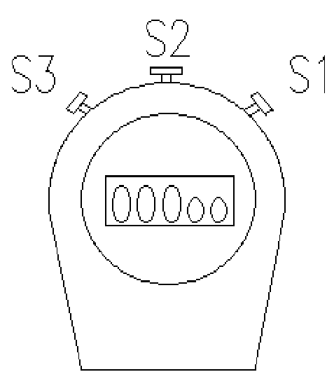
The stop-watch has three buttons: , and (see Fig. 2).
Button toggles between the date-time and the stop-watch modes. Switch to the stop-watch mode. One should see this:
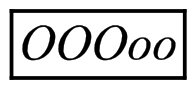
On pressing once, the stop-watch begins timing. To stop it, press a second time.
The stop-watch can be reset to zero by pressing once.
Решение
1. Theory
Let
| Quantity | Symbol |
|---|---|
| the moment of inertia of the disk be | |
| the mass of the weight | |
| the moment of the frictional force | |
| magnetic field strength | |
| the radius of the axle | |
| the moment of the magnetic force |
For the motion of the rotating disk we have:
We suppose that is constant but not negligible. Because the disk moves in the magnetic field, eddy currents are set up in the disk. The magnitude of these currents is proportional to and to the angular velocity. The Lorentz force as a result of the eddy currents and the magnetic field is thus proportional to the square of and to the angular velocity, i.e.
Substituting this into Eq. (1), we find:
After some time, the disk will reach its final constant angular velocity; the angular acceleration is now zero and for the final velocity we find:
The final constant velocity is thus a linear function of .
2. The experiment
The final constant speed is determined by measuring the time taken to fall the last [this is the width of a sheet of paper].
In the first place it is necessary to check that the final speed has been reached. This is done by allowing the weight to fall over different heights. It is clear that, with the weaker magnet, the necessary height before the constant speed is attained will be larger.
Measurements for the weak magnet system:
time taken to fall
| height (m) | smaller weight | larger weight |
|---|---|---|
| 0.30 | ||
| 0.40 | ||
| 0.50 | ||
| 0.60 | ||
| 0.70 | ||
| 0.80 | ||
| 0.90 | ||
| 1.10 | - - - | |
| 1.30 | - - - |
3. Final constant speed measurements for both magnet systems and for several choices of weight.
Measurements for the weak magnet:
| weight | T (s) | T (s) | T (s) | T (s) | (s) | (m/s) |
|---|---|---|---|---|---|---|
| small | 4.42 | 4.23 | 4.24 | 4.33 | ||
| large | 1.89 | 1.91 | 1.98 | 1.92 | ||
| both | 1.29 | 1.32 | 1.23 | 1.30 |
Measurements for the strong magnet:
| weight | T (s) | T (s) | T (s) | T (s) | (s) | (m/s) |
|---|---|---|---|---|---|---|
| small | 8.93 | 9.01 | 9.17 | 8.91 | ||
| large | 4.03 | 3.92 | 4.03 | 3.95 | ||
| both | 2.53 | 2.52 | 2.53 | 2.48 |
4. Discussion of the results:
- A graph between and the weight should be made.
- From Eq. (2) we observe that:
- both straight lines should intersect on the horizontal axis.
- from the square-root of the ratio of the slopes we have immediately the ratio of the magnetic field strengths.
- For the above measurements we find:
Marking Breakdown
| Section | Criterion | Marks |
|---|---|---|
| 1 | 1 | |
| 1 | Eq. (2) | 1 |
| 2 | Investigation of the range in which the speed is constant | 2 |
| 3 | Number of timing measurements [1,2,3,...] | 0,1,2 |
| 3 | Error estimation | 0.5 |
| 4 | graph — quality | 0.5 |
| 4 | the lines intersect each other on the mass-axis | 1 |
| 4 | calculation of | 1 |
| 4 | Error calculation | 1 |
Оригинал в Архива: ipho90.pdf · решение от архива: ipho90.pdf