IPhO 1990, Теория и експеримент — Задача 4. Determination of the efficiency of a LED.
THE 21st INTERNATIONAL PHYSICS OLYMPIAD - 1990
Внимание: Бележка към темата
Complete combined archive booklet, attributed to Hans Jordens, contains three theory questions and two experiments with keys. Printed errors and gaps are preserved: the neutron-star key changes the flattening denominator and uses a square-law radius inference; the LED key references missing graphs, has printed inconsistent table values and one unassigned final value; magnet-speed tables print m/s but their values match cm/s. Native source values and all grading remain unchanged.
Условие
Introduction
In this experiment we shall use two modern semiconductors: the light-emitting diode (LED) and the photo-diode (PD). In a LED, part of the electrical energy is used to excite electrons to higher energy levels. When such an excited electron falls back to a lower energy level, a photon with energy is emitted, where
Here is Planck's constant, is the speed of light, and is the wavelength of the emitted light. The efficiency of the LED is defined to be the ratio between the radiated power, , and the electrical power used, :
In a photo-diode, radiant energy is transformed into electrical energy. When light falls on the sensitive surface of a photo-diode, some (but not all) of the photons free some (but not all) of the electrons from the crystal structure. The ratio between the number of incoming photons per second, , and the number of freed electrons per second, , is called the quantum efficiency,
The experiment
The purpose of this experiment is to determine the efficiency of a LED as a function of the current that flows through the LED. To do this, we will measure the intensity of the emitted light with a photo-diode. The LED and the PD have been mounted in two boxes, and they are connected to a circuit panel (Fig. 1). By measuring the potential difference across the LED, and across the resistors and , one can determine both the potential differences across, and the currents flowing through the LED and the PD.
We use the multimeter to measure VOLTAGES only!! This is done by turning the knob to position 'V'. The meter selects the appropriate sensitivity range automatically. If the display is not on "AUTO" switch "off" and push on "V" again. Connection: "COM" and "V-".
The box containing the photo-diode and the box containing the LED can be moved freely over the board. If both boxes are positioned opposite to each other, then the LED, the PD and the hole in the box containing the PD remain in a straight line.
Data:
| Quantity | Value |
|---|---|
| The quantum efficiency of the photo-diode | |
| The detection surface of the PD is | |
| The wave-length of the light emitted from the LED is | |
| The internal resistance of the voltmeter is | in the range up to ; in the other ranges. |
| Planck's constant | |
| The elementary quantum of charge | |
| The speed of light in vacuo |
The range is indicated by small numbers on the display.
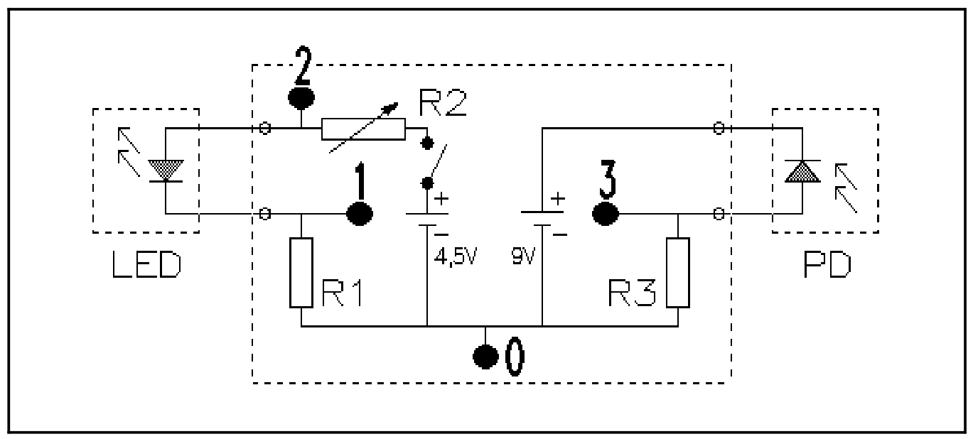
The points labelled 0, 1, 2 and 3 are measuring points.
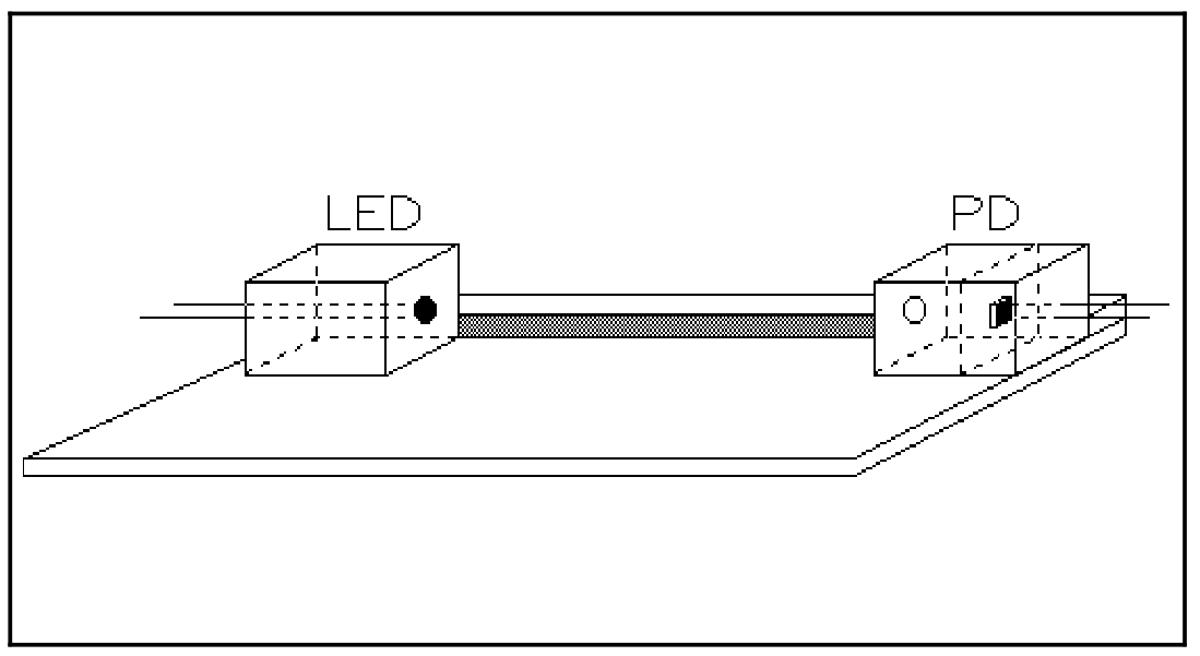
Instructions
1. Before we can determine the efficiency of the LED, we must first calibrate the photo-diode. The problem is that we know nothing about the LED.
Show experimentally that the relation between the current flowing through the photo-diode and the intensity of light falling on it, , is linear.
2. Determine the current for which the LED has maximal efficiency.
3. Carry out an experiment to measure the maximal (absolute) efficiency of the LED.
No marks (points) will be allocated for an error analysis (in THIS experiment only). Please summarize data in tables and graphs with clear indications of quantities (and units).
Решение
Внимание: Непълно решение
The retained key refers to a straight-line graph and to figure 2 of efficiency versus current, but these solution graphs are absent from all 21 original pages. All available original key text, numeric tables and marking rubric are retained. No substitute graph was invented.
1. The linearity of the photo-diode.
The linearity of the photo-diode can be checked by using the inverse square law between distance and intensity. Suppose that the measured distance between the LED and the (box containing the) PD is . The intensity of the light falling on the PD satisfies:
If the intensity is indeed proportional to the current flowing through the PD, it will also be proportional to the voltage, , measured across the resistor R3. From (1) it then follows that:
To obtain the correct value of , one should subtract from the measured voltage the voltage that one measures when the LED is turned off (but the LED box is still in place in front of the PD).
| x (cm) | (V) | (V) | (A) | (A) | () |
|---|---|---|---|---|---|
| 1.0 | 5.66 | .003 | 6.23 | .003 | 0.40 |
| 2.0 | 4.07 | .004 | 4.48 | .005 | 0.47 |
| 3.0 | 3.03 | .005 | 3.33 | .005 | 0.55 |
| 4.0 | 2.32 | .006 | 2.55 | .006 | 0.63 |
| 5.0 | 1.83 | .006 | 2.01 | .006 | 0.71 |
| 6.0 | 1.48 | .007 | 1.63 | .007 | 0.79 |
| 7.0 | 1.23 | .007 | 1.35 | .007 | 0.86 |
| 8.0 | 1.006 | .008 | 1.107 | .008 | 0.95 |
| 9.0 | 0.859 | .009 | 0.945 | .009 | 1.03 |
| 10.0 | 0.744 | .009 | 0.818 | .009 | 1.11 |
| 11.0 | 0.648 | .010 | 0.713 | .010 | 1.19 |
| 12.0 | 0.570 | .011 | 0.627 | .011 | 1.27 |
| 13.0 | 0.507 | .012 | 0.558 | .012 | 1.35 |
| 14.0 | 0.456 | .012 | 0.502 | .012 | 1.43 |
| 15.0 | 0.414 | .013 | 0.455 | .013 | 1.50 |
| 16.0 | 0.373 | .013 | 0.410 | .014 | 1.59 |
| 17.0 | 0.341 | .014 | 0.375 | .014 | 1.66 |
| 18.0 | 0.312 | .014 | 0.343 | .014 | 1.74 |
| 19.0 | 0.291 | .015 | 0.320 | .015 | 1.81 |
| 20.0 | 0.272 | .015 | 0.299 | .015 | 1.88 |
Plotted on a graph, one finds a perfect straight line.
2. The light intensity as a function of the electrical power of the LED
The photo-current is determined from the voltage over . The meter itself has an internal resistance of in the range and in the other ranges. We have then: resp. where is in volts and in .
The current in ampères through the LED is the voltage over R1 in volts, divided by 100.
PD / LED —
| PD: (V) | PD: (V) | PD: (A) | LED: ( A) | LED: (V) | LED: ( W) | |
|---|---|---|---|---|---|---|
| 1.806 | .0061 | 1.98 | 2.70 | 1.752 | 4.73 | 0.419 |
| 1.637 | .0061 | 1.79 | 2.30 | 1.742 | 4.01 | 0.446 |
| 1.511 | .0061 | 1.66 | 2.08 | 1.735 | 3.61 | 0.460 |
| 1.225 | .0061 | 1.34 | 1.606 | 1.722 | 2.77 | 0.484 |
| 1.117 | .0061 | 1.22 | 1.433 | 1.718 | 2.46 | 0.496 |
| 0.903 | .0061 | 0.99 | 1.123 | 1.705 | 1.91 | 0.518 |
| 0.711 | .0061 | 0.78 | 0.889 | 1.708 | 1.52 | 0.513 |
| 0.448 | .0061 | 0.49 | 0.555 | 1.673 | 0.93 | 0.527 |
| 0.315 | .0061 | 0.34 | 0.410 | 1.659 | 0.68 | 0.5 |
| 0.192 | .0061 | 0.21 | 0.258 | 1.637 | 0.42 | 0.2 |
The efficiency is proportional to . In the graph of against the maximal efficiency corresponds to . (See figure 2.)
3. Determination of the maximal efficiency.
The LED emits a conical beam with cylindrical symmetry. Suppose we measure the light intensity with a PD of sensitive area at a distance from the axis of symmetry. Let the intensity of the light there be , then we have:
| (mm) | (V) | (V) | ( Am) |
|---|---|---|---|
| 0 | 1.833 | 0.006 | 0 |
| 3 | 1.906 | 0.006 | 6.27 |
| 6 | 1.846 | 0.006 | 12.54 |
| 9 | 1.750 | 0.006 | 17.28 |
| 12 | 1.347 | 0.006 | 17.76 |
| 15 | 0.997 | 0.006 | 16.20 |
| 18 | 0.643 | 0.006 | 12.60 |
| 21 | 0.313 | 0.006 | 7.14 |
| 24 | 0.343 | 0.006 | 8.88 |
| 27 | 0.637 | 0.006 | 18.90 |
| 30 | 0.681 | 0.006 | 22.20 |
| 33 | 0.266 | 0.006 | 9.57 |
| 36 | 0.119 | 0.006 | 4.48 |
| 39 | 0.097 | 0.006 | |
| 42 | 0.089 | 0.006 | 4.16 |
| 45 | 0.082 | 0.006 | 3.86 |
| 48 | 0.071 | 0.006 | 3.79 |
| 51 | 0.066 | 0.006 | 3.48 |
| 54 | 0.050 | 0.006 | 3.39 |
| 57 | 0.045 | 0.006 | 2.52 |
| 60 | 0.037 | 0.006 | 2.45 |
| 63 | 0.032 | 0.006 | 2.08 |
| 66 | 0.023 | 0.006 | 1.83 |
| 69 | 0.017 | 0.006 | 1.27 |
| 72 | 0.014 | 0.006 | 0.88 |
| 75 | 0.011 | 0.006 | 0.68 |
| 0.49 |
The efficiency
Marking breakdown
| Section | Criterion | Marks |
|---|---|---|
| 1 linearity of the PD | inverse square law | 1.5 |
| 1 | number of measuring points [1,3>; [3,5>; [5,..> | 0.5/1.0/1.5 |
| 1 | dark current | 0.5 |
| 1 | correct graph | 1 |
| 2 determination of current at maximal efficiency | principle | 0.5 |
| 2 | number of measuring points [1,3>; [3,5>; [5,..> | 0.5/1.0/1.5 |
| 2 | graph efficiency-current | 0.5 |
| 2 | determination of current at maximal efficiency | 0.5 |
| 3 determination of the maximal efficiency | determination of the emitted light intensity | 1.5 |
| 3 | — via estimation of the cone cross-section | 0.5 |
| 3 | — via measurement of the intensity distribution | 1.5 |
| 3 | determination of the maximum efficiency | 1 |
Оригинал в Архива: ipho90.pdf · решение от архива: ipho90.pdf