IPhO 1991, Теория и експеримент — Задача 4. Experimental Problem
THEORETICAL PROBLEMS · 20 т.
Условие
Inside a black box provided with three terminals labeled A, B and C, there are three electric components of different nature. The components could be any of the following types: batteries, resistors larger then 100 ohm, capacitors larger than 1 microfarad and semiconductor diodes.
a) Determine what types of components are inside the black box and its relative position to terminal A, B and C. Draw the exploring circuits used in the determination, including those used to discard circuits with similar behaviour
b) If a battery was present, determine its electromotive force. Draw the experimental circuit used.
c) If a resistor was present, determine its value. Draw the experimental circuit used.
d) If a capacitor was present, determine its value. Draw the experimental circuit used.
e) If a diode was present, determine and , where the forward bias threshold voltage and is the reverse bias breakdown voltage.
f) Estimate, for each measured value, the error limits.
The following equipments and devices are available for your use:
1 back box with three terminals labeled A, B and C;
1 variable DC power supply;
2 Polytest 1 W multimeters;
10 connection cables;
2 patching boards;
1 100 kΩ, 5 % value resistor;
1 10 kΩ, 5 % value resistor;
1 1 kΩ, 5 % value resistor;
1 100 µF, 20 % value capacitor;
1 chronometer;
2 paper sheets;
1 square ruler;
1 interruptor.
Voltmeter internal resistance.
| Scale | Value in kΩ | |
|---|---|---|
| 0-1 V | 3,2 | 1 % |
| 0-3 V | 10 | 1 % |
| 0-10 V | 32 | 1 % |
| 0-20 V | 64 | 1 % |
| 0-60 V | 200 | 1 % |
Ammeter internal resistance.
| Scale | Value in Ω | |
|---|---|---|
| 0-0,3 mA | 1 000 | 1 % |
| 0-1 mA | 263 | 1 % |
| 0-3 mA | 94 | 1 % |
| 0-20 mA | 30,4 | 1 % |
| 0-30 mA | 9,84 | 1 % |
| 0-100 mA | 3,09 | 1 % |
| 0-300 mA | 0,99 | 1 % |
| 0-1 mA | 0,31 | 1 % |
Notice: Do not use the Polystes 1 W as an ohmmeter. Protect your circuit against large currents, and do not use currents larger than 20 mA.
Give your results by means of tables or plots.
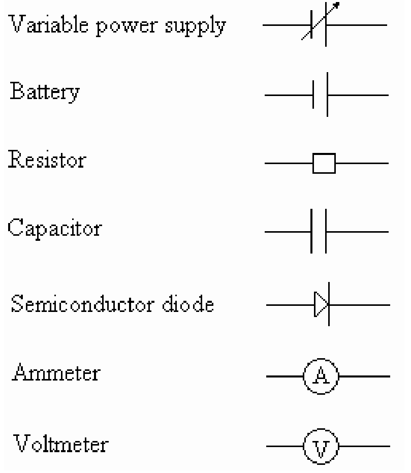
When drawing the circuits, use the following symbols:
Решение
Since a battery could be present, the first test should be intended to detect it. To do that, the voltage drops , and should be measured using a voltmeter. This test will show that no batteries are present.
Next, a testing circuit as shown in figure 4.1 should be used.
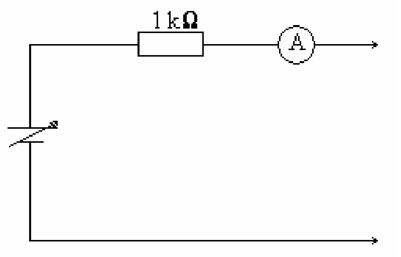
By means of this circuit, the electric conduction between a pair of terminals should be tested, marking all permutations and reversing the polarity. Resistor is included to prevent a large current across the diode. One conclusion is that between A and C there is a diode and a resistor in series, although its current position is still unknown. The other conclusion is that a capacitor is tighted to terminal B. To determine the actual circuit topology, further transient experiments have to be conducted.
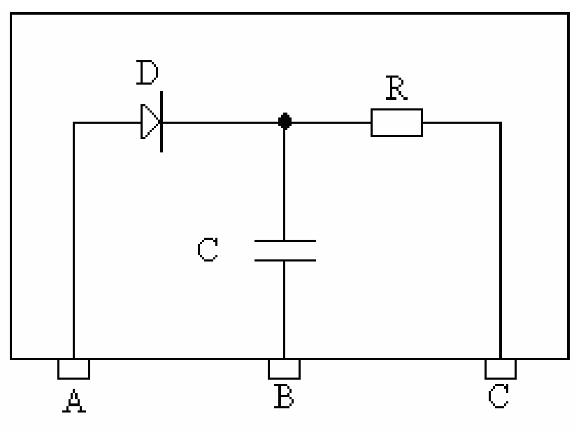
In this way, it is concluded that the actual circuit inside the black box is that shown in figure 4.2.
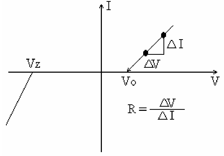
The best procedure for the resistor value determination is to plot a set of voltage and current values measured between A and C. Figure 4.3 shows the resulting plot. Extrapolating both linear regions, the values of and are obtained and the resistor value equals the reciprocal of the slope.
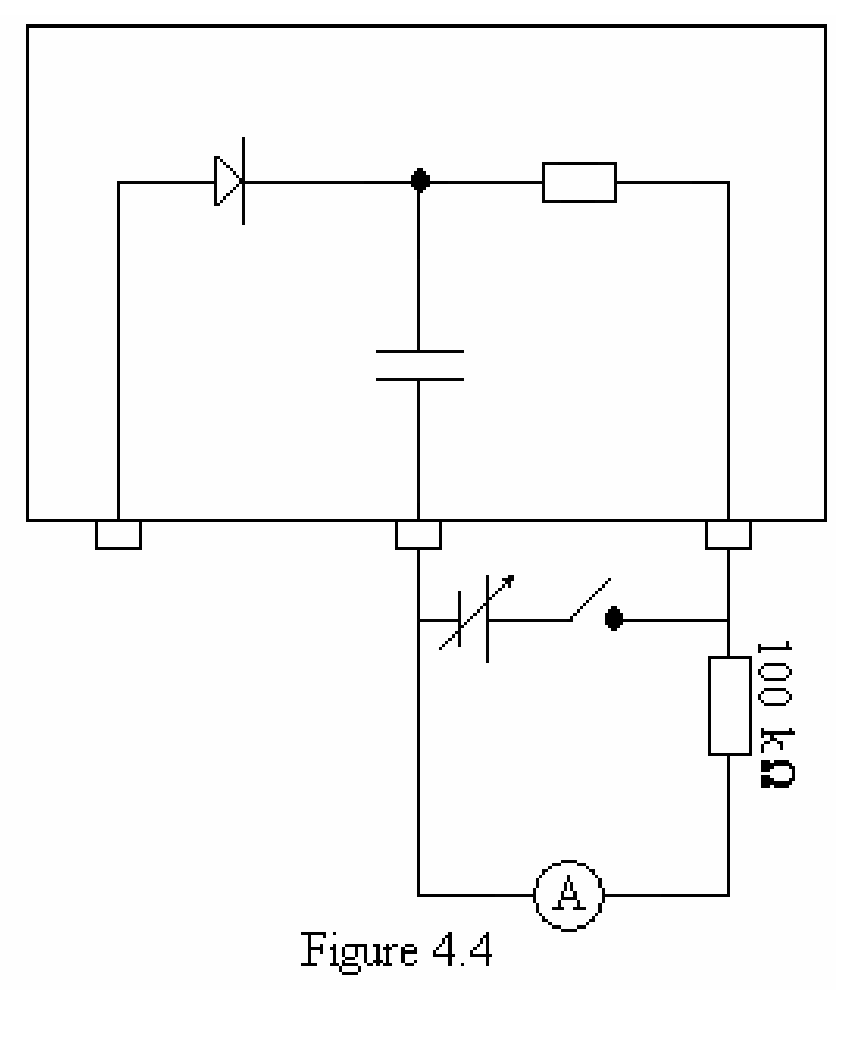
Similar, the best method to measure the capacitor value is to build a testing circuit as shown in figure 4.4. The current is adjusted to full scale and then, the switch is opened.
The time needed by the current to drop to its half value is measured. Applying the formulae t = RCIn(2), the value of C is obtained.
Marking Code
- Determination of circuit topology: 8 points.
- 1.1 For discarding the presence of a battery: 1 point.
- 1.2 For drawing the exploring circuit which determine the circuit topology in a unique way: 7 points.
- Resistor and diode parameters value measurement: 8 points.
- 2.1 For drawing the measuring circuit: 2 points.
- 2.2 Error limits calculation: 3 points.
- 2.3 Result: 3 points.
- 2.3.1 Coarse method: 2 points.
- 2.3.2 Graphic method: 3 points.
- Capacitor value measurement: 4 points.
- 3.1 For drawing the measuring circuit: 2 points.
- 3.2 Error limits calculations: 2 points.
Оригинал в Архива: ipho91.pdf