Съдържание
УсловиеApparatusPart 1 · Displacement and hysteresis1.1 · Circuit · 1 point1.2 · Geometry · 1 point1.3 · Displacement formula · 2 points1.4 · Graph · 2 points1.5 · Energy · 1 point1.6 · Value and uncertainty · 1.5 pointsPart 2 · Voltage and length dependence2.1 · Exponent m · 1 point2.2 · Exponent n · 1.5 points2.3 · Constant A · 3 pointsPart 3 · Capacitance3.1 · Circuit · 1 point3.2 · Method · 3 points3.3 · Capacitance value · 2 pointsРешениеIPhO 1997, Експеримент — Задача 1. Characterization of the bimorph
Characterization of the bimorph · 15 юли 1997 г. · 20 т.
Внимание: Бележка към темата
В оригиналните изображения липсват част от символите и схемата за измерване на капацитета в Част 3. Липсите са отбелязани в текста; графиките и оцелелите схеми са запазени без замяна с предполагаеми изображения.
Read this first
28th International Physics Olympiad, Sudbury, Canada. Experimental competition, Tuesday, July 15th, 1997. Time available: 5 hours.
- Use only the pen provided.
- Use only the front side of the answer sheets and paper.
- Read page 4 before touching any of the apparatus, in particular be extremely careful in handling the bimorph.
- In your answers please use as little text as possible; express yourself primarily in equations, numbers and figures.
- Please indicate on the first page the total number of pages you used.
- At the end of the exam please put your answer sheets, pages and graphs in order.
This problem consists of 11 pages.
Examination prepared at: University of British Columbia, Department of Physics and Astronomy. Hosted by: Laurentian University and Science North.
Условие
Warning: Do not look directly into the laser beam or into the laser beam reflected from the mirror — it may damage your vision.
The bimorph consists of two layers of piezoelectric material bonded together. Metal electrodes have been evaporated onto the two outer surfaces to allow the application of an electric field (see Fig. 1). The layers are chosen in such a way that when an electric field is perpendicular to the outer surfaces, one of them expands (along ), while the other contracts (along ). Reversing the field reverses the effect on the layers: the one which previously contracted expands while the other one contracts. Assume that upon the application of the field the bimorph bends into a circular arc.
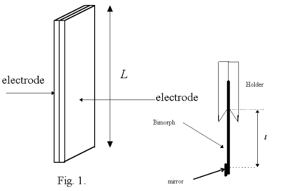
Note: Piezoelectric materials change their dimensions while in an electric field and produce an electric potential when under mechanical strain. The relative change of a given dimension in the electric field is, in first approximation, proportional to the field; there is however some hysteresis which means that if one applies the field and then reduces it back to zero the dimensions will not return to exactly the original values. One has to apply some small field in the opposite direction to restore the dimensions to the original value. The force expanding or contracting the piezoelectric material is, in first approximation, proportional to the field.
Apparatus
- A bimorph of length , with a small mirror attached to one end, clamped in the holder (clothes pin) with attached contacts and leads. You can change the length of the free part of the bimorph by moving it in the holder. Be careful, the bimorph is delicate!
- A laser pointer (with a rubber band around it, which can be used to keep the switch on during the measurements).
- Black modelling clay to fix the bimorph holder and the laser pointer on the table.
- A screen (use the graph paper which you can attach to the partition around the table).
- A multimeter with cables. To measure DC voltage with this multimeter rotate the switch to the position in which the little circle points at 200 in the area marked DCV. The input impedance for the voltage measurements is printed as 1 M [unit symbol missing in source], accuracy of the measurement is 0.1 V.
- A variable resistor (potentiometer), printed as 2.5 M [unit symbol missing in source], to control the bimorph’s voltage, with three leads. The red lead is connected to the central (moving) electrode of the potentiometer.
- A pack of four 9 V batteries with leads. Note: the resistance of the battery pack was increased by adding a 5 k [unit symbol missing in source] resistor in series with one of the leads. This is to limit the current and protect the circuit. DO NOT short or bypass this resistor.
- A resistor printed as G [unit symbol missing in source]. Note: the resistance of this resistor can be affected by the residue from your skin; do not touch the body of the resistor, only the metal wires.
- A stop watch.
- A ruler.
- Masking tape.
Part 1 · Displacement and hysteresis
Determine the dependence of the displacement of the bimorph’s free end as a function of the applied voltage in the range from +36 V down to −36 V and back up to +36 V. During these measurements, change the voltage only in the indicated direction (for example, when you measure in the range from −36 V to +36 V always increase the voltage and never decrease it; if you miss a point, skip it). Demonstrate this dependence with a graph.
During one cycle of applied voltage from +36 V to −36 V and back to +36 V a certain amount of energy is dissipated in the bimorph itself. Identify and calculate a quantity which is proportional to this amount of energy.
1.1 · Circuit · 1 point
Draw a diagram of the circuit you used to determine the displacement of the free end of the bimorph versus voltage.
1.2 · Geometry · 1 point
Draw a schematic diagram showing the geometry of the setup and label all the relevant quantities.
1.3 · Displacement formula · 2 points
Give the formula relating the displacement of the bimorph’s free end to the measured quantities. Enter the formula here with all the variables explained, referring to the diagram in 1.2, and enter the number of the page containing the derivation of this formula.
1.4 · Graph · 2 points
Demonstrate the dependence of the displacement of the free end of the bimorph on the voltage on the graph paper provided. Indicate which points correspond to measurements made while increasing voltage and those made while decreasing voltage. Remember to label the axes including the values and units. Write down the number of the page containing the graph.
1.5 · Energy · 1 point
Identify a quantity proportional to the energy dissipated in the bimorph.
1.6 · Value and uncertainty · 1.5 points
Enter here the value of the quantity proportional to the energy dissipated in the bimorph, its error and units.
Part 2 · Voltage and length dependence
For a given bimorph, if the hysteresis is neglected, the displacement of the bimorph’s free end is given by the formula
where is the applied voltage, the length of the bimorph’s free end (measured from the edge of the contacts in the holder), and , and are constants. Find, by performing the necessary measurements and calculations, the constants , and .
2.1 · Exponent m · 1 point
Enter here the value for m. Enter the numbers of the pages containing data tables, graphs and calculations used to determine this value.
2.2 · Exponent n · 1.5 points
Enter here the value for n with error. Enter the numbers of the pages containing data tables, graphs and calculations used to determine this value.
2.3 · Constant A · 3 points
Enter here the value of the constant A, its error and units.
Part 3 · Capacitance
Measure the capacitance of the bimorph.
3.1 · Circuit · 1 point
Draw a diagram of the circuit you used to measure the capacitance of the bimorph.
3.2 · Method · 3 points
Write down the quantities you measured and the formula you used to determine the capacitance of the bimorph. Write down the numbers of the pages containing the diagrams, graphs and data tables.
3.3 · Capacitance value · 2 points
Enter here the value of the capacitance, its error and units.
Решение
Внимание: Непълно решение
Официалното решение е непълно.
The surviving official solution is reproduced below. Its circuit image for Part 3 is missing, and several angle and unit symbols were lost in the original HTML screenshots. Missing symbols are marked explicitly; the original diagrams and graphs are retained.
1.1 · Voltage circuit
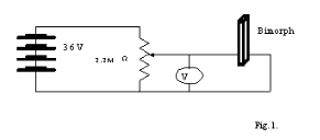
1 point for any diagram which allows applying the full range of voltages.
1.2 · Geometry
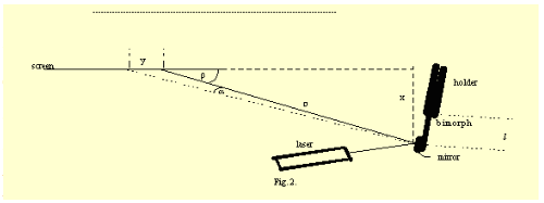
is the distance from the mirror to the spot on the screen. is the distance the spot moves when voltage is applied, is the shortest distance from the mirror to the screen.
1 point for any well-labelled arrangement allowing the experiment to be performed with reasonable sensitivity.
1.3 · Displacement
is the length of the free part of the bimorph. See Fig. 2 for , and .
When the bimorph bends into an arc shape, the mirror at the end is rotated by an angle [symbol missing]/2. This results in a change of direction of the reflected beam by an angle [symbol missing]. The spot formed by the reflected beam on the screen moves by a distance (see Fig. 2). If the angle between the reflected beam and the screen is [symbol missing] (less than 90 degrees to increase accuracy), the small angle [symbol missing] by which the laser beam is deflected due to the movement of the bimorph is given in the source as:
The angle of rotation of the mirror [symbol missing]/2 is related to the deflection of the free end of the bimorph by (see Fig. 3). For small [symbol missing] we have
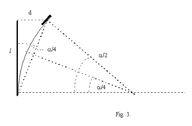
2 points (also for any other correct formula relating the displacement to the measured quantities). 1 point for the formula with 1 error, 1/2 for the formula with two errors, 0 for the formula with more errors. Total 2 points.
1.4 · Displacement versus voltage
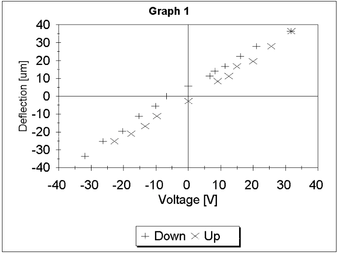
2 points for a correct graph.
1.5 · Dissipated energy
The force moving the bimorph is proportional to the applied voltage , the distance is proportional to the displacement , so the area under the plot of versus is proportional to the energy. Therefore the area inside the hysteresis curve is proportional to the energy dissipated in the bimorph.
1 point for identifying the area inside the hysteresis curve as proportional to the energy dissipated in the bimorph.
1.6 · Hysteresis-loop area
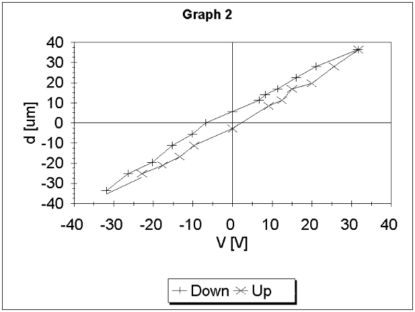
Graph 2 shows the data from Graph 1 with the hysteresis curve outlined. Area must be expressed in the units of the x axis times units of the y axis. The area estimated from Graph 2 is printed as ; the source does not render the prefix symbol between V and m.
If the quantity is correctly identified and the value consistent to within 50% with the student’s data, 1 point will be given. No points will be allocated for the value if the units are not specified. 1/2 point for a reasonable error estimate. Total 1.5 points.
2.1 · Voltage exponent
If hysteresis is ignored, the data from Graph 1 can be fitted with a straight line, indicating that the displacement is proportional to voltage. See Graph 3.
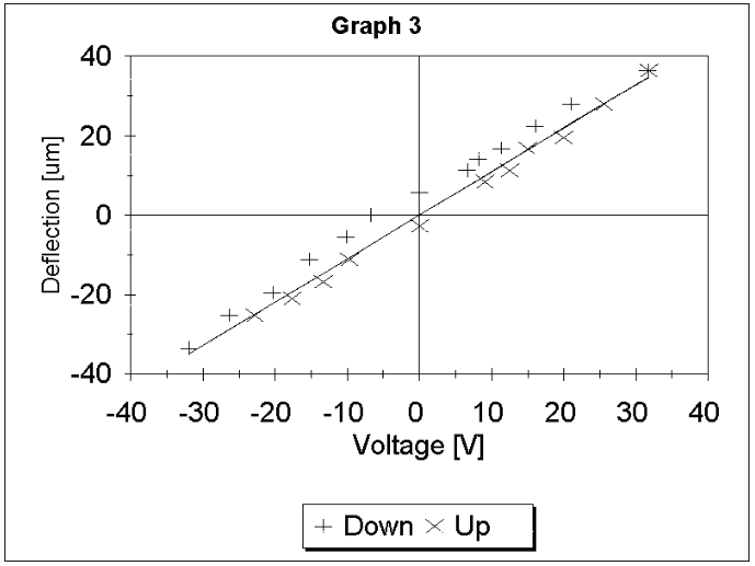
1 point for showing that .
2.2 · Length exponent
Graph 4 shows the dependence of the displacement of the end of the bimorph on the length of the bimorph for the same voltage change, 72 V.
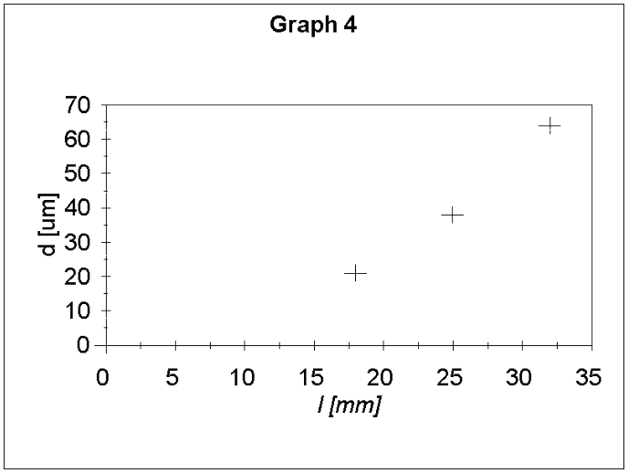
One can conclude from this graph that the displacement is not proportional to the length. One can then plot versus (see Graph 5) and calculate the slope, which will give the value of . From Graph 5 we obtain . Notice that should be measured from the centre of the mirror to the edge of the holder.
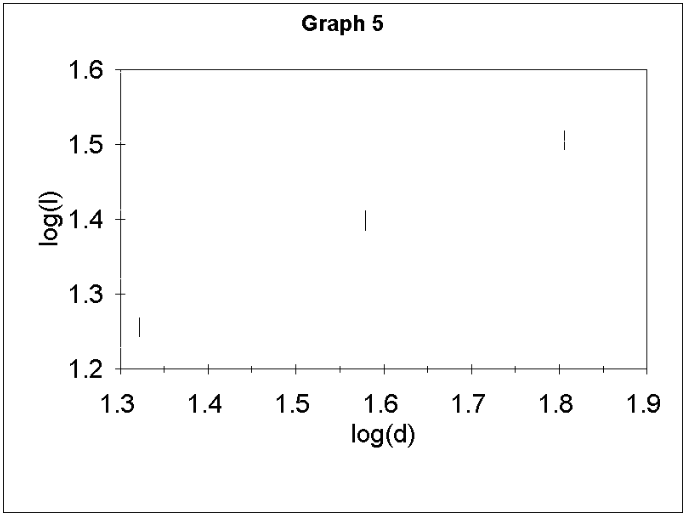
1 point for demonstrating by correct measurements and graph and/or calculations that is about 2 (between 1.7 and 2.3). 1/2 point for values between 1.5 and 1.7 or 2.3 and 2.5. 1/2 point for a reasonable error estimate, for example from the range of possible slopes on Graph 5. Total 1.5 points.
Source discrepancy: the printed Graph 5 labels its horizontal axis log(d) and vertical axis log(l), although the accompanying text specifies log(d) versus log(l). The original figure and text are preserved.
2.3 · Constant A
Knowing , and , one can calculate from the slope of the straight line on Graph 2.
| Printed coefficient range | Points |
|---|---|
| 7 to 11 | 2 |
| 5 to 13, outside the region above | 1 |
| 2 to 16, outside the regions above | 1/2 |
1 point for a reasonable error estimate, for example from the range of possible slopes on Graph 3. Total 3 points.
Source note: the reference to “Graph 2” above is printed in the original solution.
3.1 · Capacitance circuit
Missing source image: the original screenshot displays a broken image in place of this circuit diagram. No replacement circuit is supplied here.
1 point for this or equivalent schematics utilizing the resistor printed as 1 G [unit symbol missing] in such a way that the time constant is of the order of seconds. 1/2 point for other arrangements that could measure the capacitance. Total 1 point.
3.2 · RC decay
The resistor printed as 1 G [unit symbol missing] and the bimorph form an RC circuit. If we charge the capacitance of the bimorph to maximum voltage () and disconnect the battery, the voltage will decay according to the formula
where is elapsed time. If the voltmeter with the input resistance printed as 1 M [unit symbol missing] is connected to the bimorph to measure the voltage directly, the time constant is too short to be measured. The deflection of the bimorph is proportional to the voltage, so one can measure the decay time indirectly by observing the decay of the deflection after the bimorph was charged. To do so efficiently, one can mark several points on the screen between the deflections corresponding to the maximum voltage and 0 voltage and measure the time the deflection takes to decay to these points. The slope of the plot of logarithm of deflection versus time (Graph 6), or the equivalent calculations, will give the time constant; knowing , one can obtain .
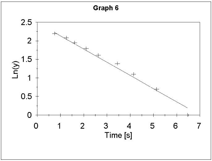
1 point for a correct formula for . 1 point for using the time-dependent displacement as a measure of the time constant. 1 point for a correct data table and/or graph. Total 3 points.
3.3 · Capacitance
| Capacitance range (nF) | Points |
|---|---|
| 3 to 7 | 1.5 |
| 1 to 9, outside the region above | 1 |
| 0.5 to 12, outside the regions above | 1/2 |
No points will be allocated for the value if the units are not specified. 1/2 point for a reasonable error estimate. Total 2 points.
Оригинал в Архива: exp_1.png · официални решения: exp_sol1.png · допълнителни данни: exp_2.png · допълнителни данни: exp_3.png · допълнителни данни: exp_sol2.png · допълнителни данни: exp_sol3.png · допълнителни данни: exp_sol4.png · допълнителни данни: exp_sol5.png · допълнителни данни: exp_sol6.png · допълнителни данни: exp_sol7.png · допълнителни данни: exp_sol8.png · допълнителни данни: exp_sol9.png · допълнителни данни: exp_sol10.png