IPhO 2003, Експеримент — Задача 1. Part A: Optical Properties of Laser Diode
The 34th International Physics Olympiad — Taipei, Taiwan — Experimental Competition — Wednesday, August 6, 2003 · 6 август 2003 г. · 5 т.
Please Read This First:
- Use only the pen provided.
- Use only the front side of the answer sheets and paper.
- In your answers please use as little text as possible; express yourself primarily in equations, numbers and figures. If the required result is a numerical number, underline your final result with a wavy line.
- Write on the blank sheets of paper the results of your measurements and whatever else you consider is required for the solution of the question and that you wish to be marked.
- It is absolutely essential that you enter in the boxes at the top of each sheet of paper used your Country and your student number [Student No.]. In addition, on the blank sheets of paper used for each question, you should enter the question number [Question No. : e.g. A-(1)], the progressive number of each sheet [Page No.] and the total number of blank sheets that you have used and wish to be marked for each question [Total No. of pages]. If you use some blank sheets of paper for notes that you do not wish to be marked, put a large cross through the whole sheet and do not include them in your numbering.
- At the end of the exam please put your answer sheets and graphs in order.
- Error bars on graphs are only needed in part A of the experiment.
- Caution: Do not look directly into the laser beam. You can damage your eyes!!
Условие
Apparatuses and materials
- Available apparatuses and materials are listed in the following table:
| Item | Apparatus & material | Quantity | Item | Apparatus & material | Quantity |
|---|---|---|---|---|---|
| A | Photodetector (PD) | 1 | I | Batteries | 2 |
| B | Polarizers with Rotary mount | 2 | J | Battery box | 1 |
| C | 90˚ TN-LC cell (yellow wires) with rotary LC mount | 1 | K | Optical bench | 1 |
| D | Function generator | 1 | L | Partially transparent papers | 2 |
| E | Laser diode (LD) | 1 | M | Ruler | 1 |
| F | Multimeters | 2 | N | White tape * (for marking on apparatus) | 1 |
| G | Parallel LC cell (orange wires) | 1 | O | Scissors | 1 |
| H | Variable resistor | 1 | P | Graph papers | 10 |
* Do not mark directly on apparatus. When needed, stick a piece of the white tape on the parts and mark on the white tape.
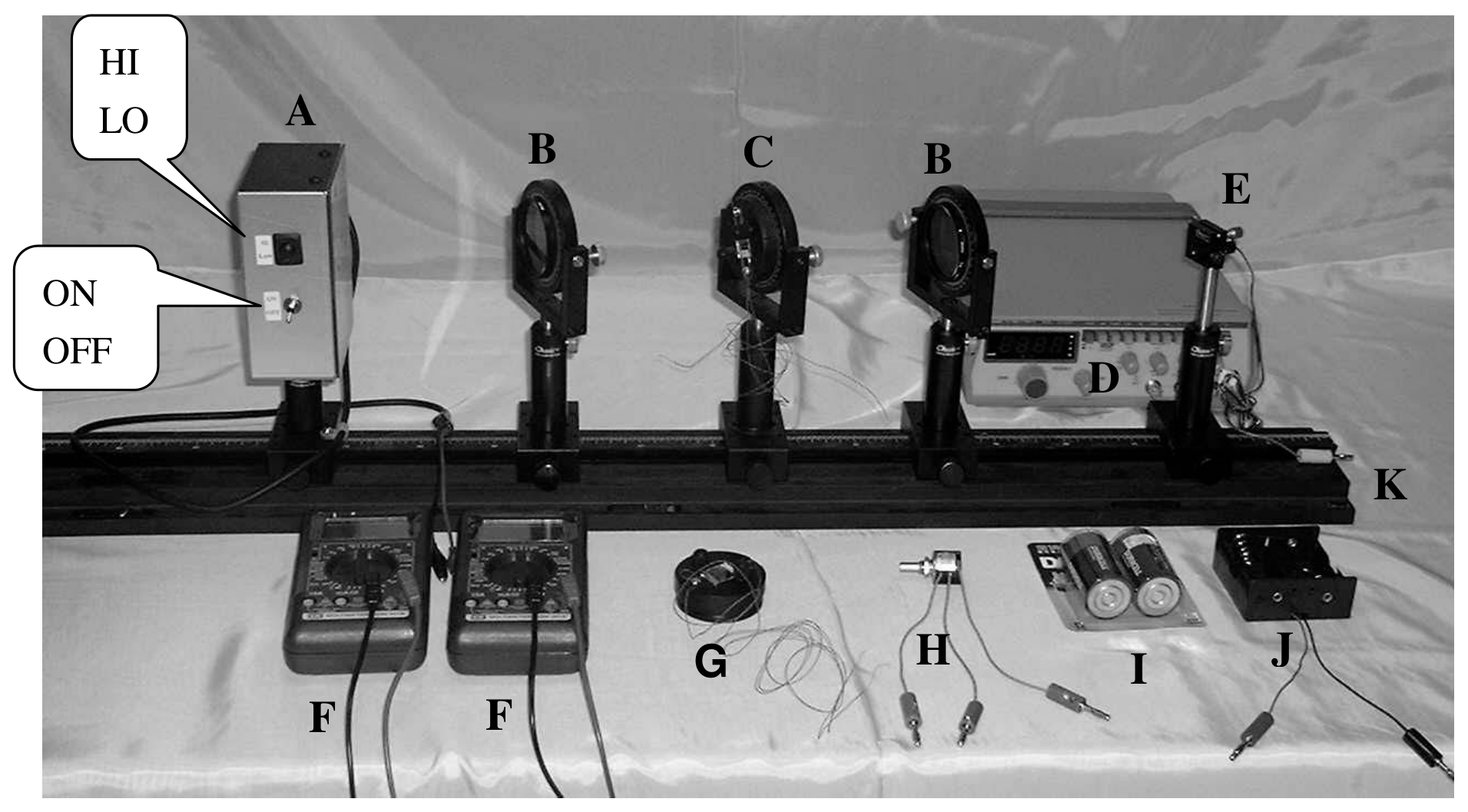
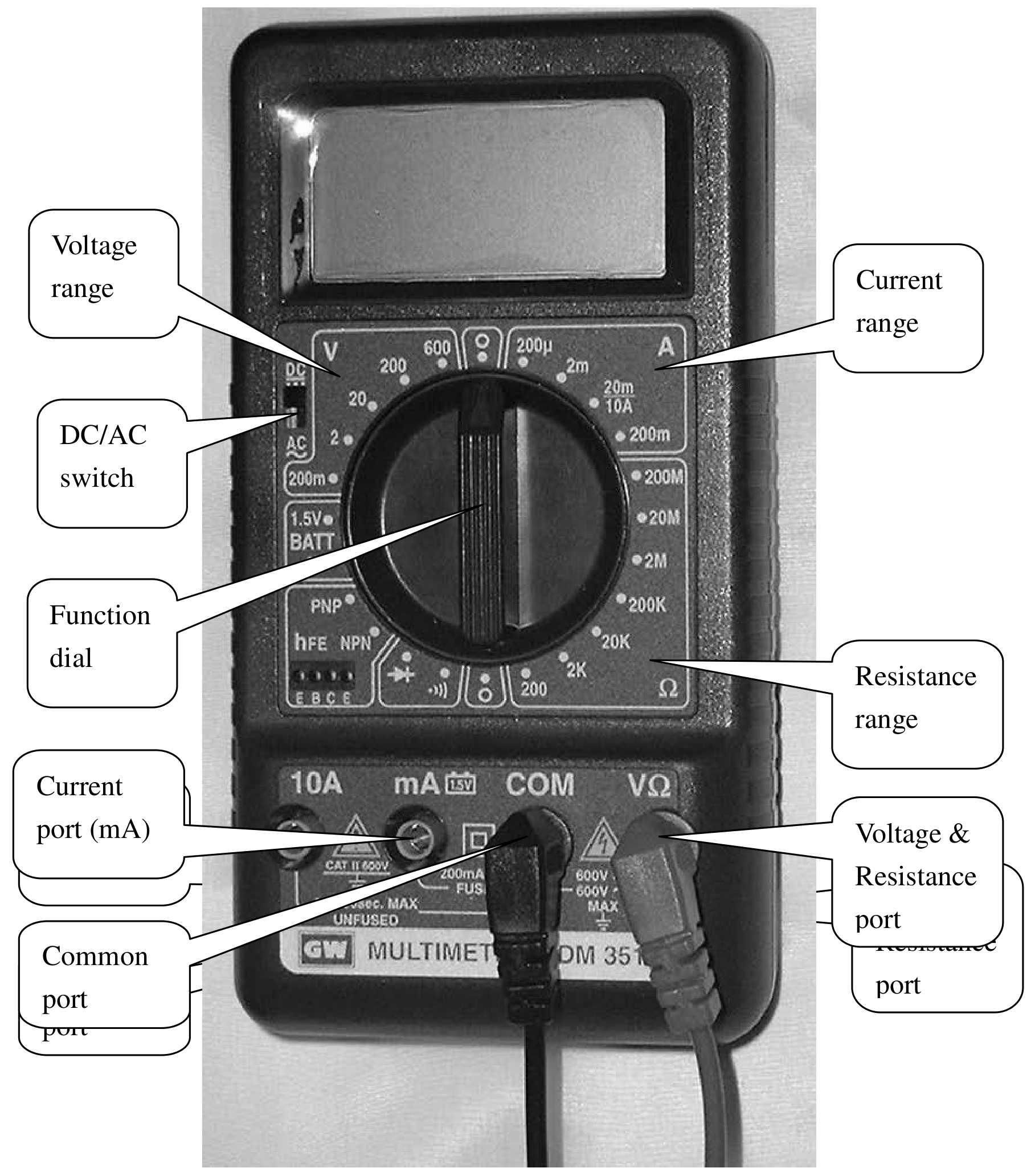
- Instructions for the multimeter:
- “DC/AC” switch for selecting DC or AC measurement.
- Use the “VΩ” and the “COM” inlets for voltage and resistance measurements.
- Use the “mA” and the “COM” inlets for small current measurements. The display then shows the current in milliamperes.
- Use the function dial to select the proper function and measuring range. “V” is for voltage measurement, “A” is for current measurement and “Ω”is for resistance measurement.
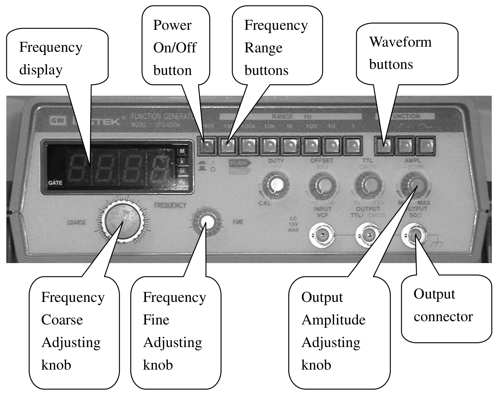
- Instructions for the Function Generator:
- The power button may be pressed for “ON” and pressed again for “OFF”
- Select the frequencies range, and press the proper button.
- The frequency is shown on the digital display.
- Use the coarse and the fine frequency adjusting knobs to tune the proper frequency.
- Select the square-wave form by pressing the left most waveform button.
- Use the amplitude-adjusting knob to vary the output voltage.
Part A: Optical Properties of Laser Diode
I. Introduction
- Laser Diode
The light source in this experiment is a laser diode which emits laser light with wavelength 650 nm. When the current of the laser diode (LD) is greater than the threshold current, the laser diode can emit monochromatic, partially polarized and coherent light. When the current in the laser diode is less than the threshold, the emitted light intensity is very small. At above the threshold current, the light intensity increases dramatically with the current and keeps a linear relationship with the current. If the current increases further, then the increasing rate of the intensity with respect to the current becomes smaller because of the higher temperature of the laser diode. Therefore, the optimal operating current range for the laser diode is the region where the intensity is linear with the current. In general, the threshold current is defined as the intersection point of the current axis with the extrapolation line of the linear region.
Caution: Do not look directly into the laser beam. You can damage your eyes!!
- Photodetector
The photodetector used in this experiment consists of a photodiode and a current amplifier. When an external bias voltage is applied on the photodiode, the photocurrent is generated by the light incident upon the diode. Under the condition of a constant temperature and monochromatic incident light, the photocurrent is proportional to the light intensity. On the other hand, the current amplifier is utilized to transfer the photocurrent into an output voltage. There are two transfer ratios in our photodetector – high and low gains. In our experiment, only the low gain is used. However, because of the limitation of the photodiode itself, the output voltage would go into saturation at about 8 Volts if the light intensity is too high and the photodiode cannot operate properly any more. Hence the appropriate operating range of the photodetector is when the output voltage is indeed proportional to the light intensity. If the light intensity is too high so that the photodiode reaches the saturation, the reading of the photodetector can not correctly represent the incident light intensity.
II. Experiments and procedures
Characteristics of the laser diode & the photodetector
In order to make sure the experiments are done successfully, the optical alignment of light rays between different parts of an experimental setup is crucial. Also the light source and the detector should be operated at proper condition. Part A is related to these questions and the question of the degree of polarization.
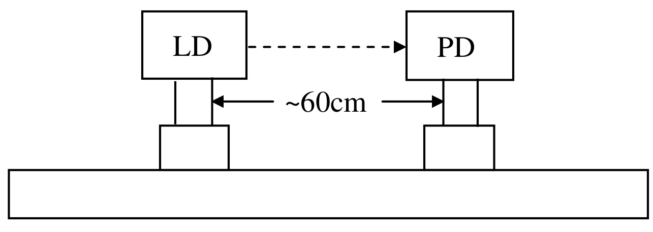
- Mount the laser diode and photodetector in a horizontal line on the optical bench, as shown in Fig. 4. Connect the variable resistor, battery set, ampere meter, voltage meter, laser diode and photodetector according to Fig. 5. Adjust the variable resistor so that the current passing through LD is around 25 mA and the laser diode emits laser light properly. Choose the low gain for the photodetector. Align the laser diode and the photodetector to make the laser light level at the small hole on the detector box and the reading of the photodetector reaches a maximum value.
Caution: Do not let the black and the red leads of the battery contact with each other to avoid short circuit.
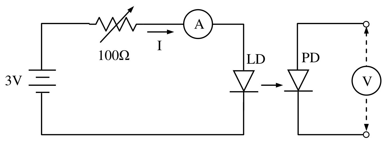
- Use the output voltage of the photodetector to represent the laser light intensity . Adjust the variable resistor to make the current of the laser diode varying from zero to a maximum value and measure the as increases. Be sure to choose appropriate current increment in the measurement.
A-(1) Measure, tabulate, and plot the vs. curve. [1,5 т.]
A-(2) Estimate the maximum current with uncertainty in the linear region of the vs. curve. Mark the linear region on the - curve figure by using arrows (↓) and determine the threshold current with uncertainty. [3,5 т.]
Choose the current of the laser diode as to make sure the laser diode and photodetector are operated well.
To prepare for the part B experiment: Mount a polarizer on the optical bench close to the laser diode as shown in Fig. 6. Make sure the laser beam passing through the center portion of the polarizer. Adjust the polarizer so that the incident laser beam is perpendicular to the plane of the polarizer. (Hint: You can insert a piece of partially transparent paper as a test screen to check if the incident and reflected light spots coincide with each other.)
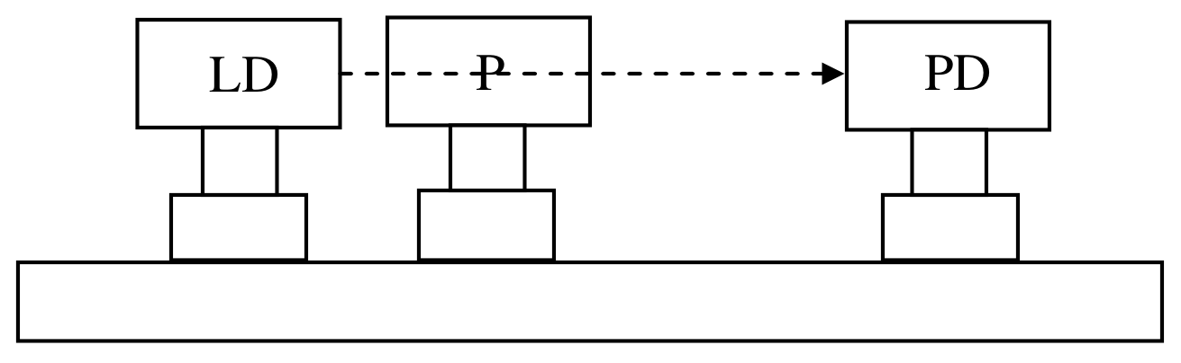
- Keep the current of the laser diode unchanged, mount a second piece of polarizer on the optical bench and make sure proper alignment is accomplished, i.e., set up the source, detector and polarizers in a straight line and make sure each polarizer plane is perpendicular to the light beam.
Отговори
A-(2) Ith = 23.48 ± 0.03 mA (least-square method); Ith = 23.5 ± 0.2 mA (eye-balling method)
The official solution accepts Ith = (21~26) ± (0.01 or 0.2 for single value) mA.
Решение
Solutions to Experimental Problems
Part A: Optical Properties of Laser Diode
Question A-(1) (Total 1.5 point)
Measure, tabulate, and plot the vs. curve.
a. Data (0.3 pts.) : Proper data table marked with variables and units.
Table A-(1): Data for vs. .
| (mA) | 9.2 | 15.2 | 19.5 | 21.6 | 22.2 | 22.7 | 23.0 | 23.4 | 23.8 |
|---|---|---|---|---|---|---|---|---|---|
| (V) | 0.00 | 0.01 | 0.02 | 0.03 | 0.05 | 0.06 | 0.09 | 0.12 | 0.30 |
| (mA) | 24.2 | 24.6 | 25.0 | 25.4 | 25.8 | 26.2 | 26.6 | 27.0 | 27.4 |
| (V) | 0.66 | 1.02 | 1.41 | 1.88 | 2.23 | 2.64 | 3.04 | 3.36 | 3.78 |
| (mA) | 27.8 | 28.2 | 28.6 | 29.0 | 29.4 | 29.8 | 30.2 | 30.5 | 31.0 |
| (V) | 4.12 | 4.48 | 4.79 | 5.13 | 5.44 | 5.72 | 6.05 | 6.25 | 6.55 |
| (mA) | 31.4 | 31.8 | 32.2 | 32.6 | 33.0 | 33.4 | 33.8 | 34.2 | 34.6 |
| (V) | 6.75 | 6.99 | 7.22 | 7.40 | 7.60 | 7.78 | 7.93 | 8.07 | 8.14 |
| (mA) | 35.0 | 35.5 | 36.0 | 36.5 | 37.0 | 37.6 | 38.0 | 38.6 | |
| (V) | 8.18 | 8.20 | 8.22 | 8.24 | 8.24 | 8.25 | 8.26 | 8.27 |
Current error : ±0.1 mA; Voltage error : ±0.01 V
b. Plotting (0.3 pts.): Proper sizes of scales, and units for abscissa and ordinate that bear relation to the accuracy and range of the experiment.
c. Curve (0.9 pts.): Proper data and adequate line shape
- As shown in Fig. A-1. Start ~0 → Threshold → Linear → Saturate.
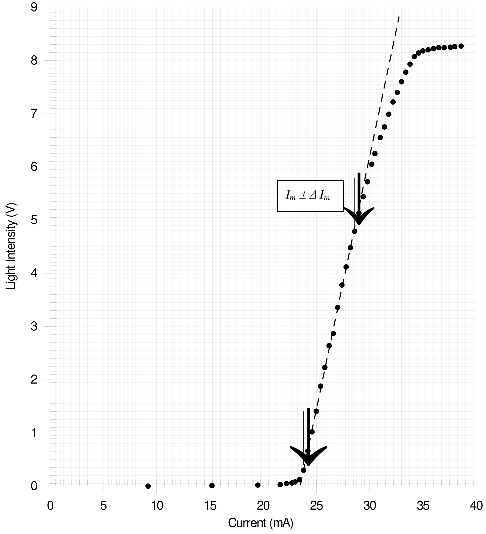
Question A-(2) ( Total 3.5 points)
Estimate the maximum current with uncertainty in the linear region of the - . Mark the linear region on the - curve figure by using arrows (↓) and determine the threshold current with detailed error analysis.
a. Linear region marking (0.5 pts.) in Fig. A-1.
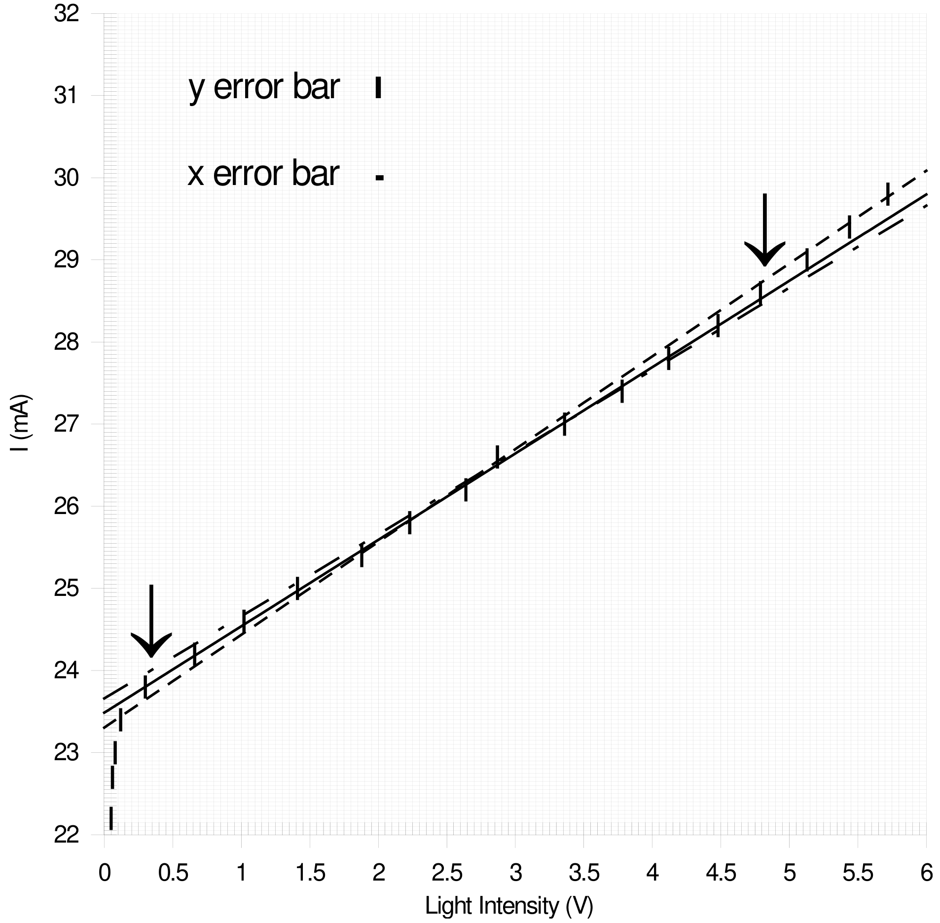
b. Least-square method or eye-balling with ruler and error analysis (1.5 pt.)
| Least-square fitting | Eye-balling with ruler |
|---|---|
| Error bar in graph 0.0x mA (0.5 pts) | Error bar in graph 0.x mA (0.5 pts) |
| Least-square method (0.5 pts) | Expanded scale graph (0.5 pts) |
| Error analysis (0.5 pts) | draw three lines for error analysis(0.5 pts) |
c. (0.5 pts.): Adequate value of (0.3 pts.) and error( ) (0.2 pts.) from the linear region of -I curve.
d. Adequate value of with error (1.0 pts.)
= (21~26) ± (0.01 or 0.2 for single value) mA
Adequate value of (0.5 pts.) and error ( ) (0.5 pts.)
Appendix:
◎A1-1
- Least-Square Method:
For
| : (mA) | : | |||||
|---|---|---|---|---|---|---|
| 1 | 23.8 | 0.30 | 7.14 | 0.090 | 23.7937 | 3.969E-05 |
| 2 | 24.2 | 0.66 | 15.972 | 0.4356 | 24.17134 | 0.000821 |
| 3 | 24.6 | 1.02 | 25.092 | 1.0404 | 24.54898 | 0.00260 |
| 4 | 25.0 | 1.41 | 35.25 | 1.9881 | 24.95809 | 0.00176 |
| 5 | 25.4 | 1.88 | 47.752 | 3.5344 | 25.45112 | 0.00261 |
| 6 | 25.8 | 2.23 | 57.534 | 4.9729 | 25.81827 | 0.000334 |
| 7 | 26.2 | 2.64 | 69.168 | 6.9696 | 26.24836 | 0.00234 |
| 8 | 26.6 | 3.04 | 80.864 | 9.2416 | 26.66796 | 0.00462 |
| 9 | 27.0 | 3.36 | 90.72 | 11.2896 | 27.00364 | 1.325E-05 |
| 10 | 27.4 | 3.78 | 103.572 | 14.2884 | 27.44422 | 0.00196 |
| 11 | 27.8 | 4.12 | 114.536 | 16.9744 | 27.80088 | 7.744E-07 |
| 12 | 28.2 | 4.48 | 126.336 | 20.0704 | 28.17852 | 0.000461 |
| 13 | 28.6 | 4.79 | 136.994 | 22.9441 | 28.50371 | 0.00927 |
| = 340.6 | = 33.71 | = 910.93 | = 113.840 | = 0.0268 |
◎A1-2
- Eye-balling Method:
For
Line 1:
Line 2:
Line3:
(av.) = 23.48
(std.) = 0.18
Marking Scheme
Part A: Optical Properties of Laser Diode
| No. | Contents | Sub Scores | Total Scores |
|---|---|---|---|
| A(1) | Measure, tabulate, and plot the vs. curve. | 1.5 pts. | |
| a | Proper data table marked with variables and units. | 0.3 | |
| b | Proper sizes of scales, and units for abscissa and ordinate that bear relation to the accuracy and range of the experiment. | 0.3 | |
| c | Proper data and adequate curve plotting (Fig. A-1) | 0.9 | |
| A(2) | Estimate the maximum current with uncertainty in the linear region of the vs. curve. Mark the linear region on the - curve figure by using arrows (↓) and determine the threshold current with uncertainty. | 3.5 pts. | |
| a | Mark the linear region. | 0.5 | |
| b | Least-square fit or eye-balling with ruler and error analysis | 1.5 | |
| c | Obtain properly | 0.5 | |
| d | Adequate value of | 1.0 |
Оригинал в Архива: IPhO_2003_Experiment Question.pdf · официални решения: IPhO_2003_Experiment Solution.pdf