IPhO 2014, Експеримент — Задача 1. Part 1.Qualitative observations!
Experimental competition. Thursday, 17 July 2014 — Experiment. To see invisible! (20 points) · 17 юли 2014 г. · 3,5 т.
Условие
Experiment. To see invisible! (20 points)
Introduction
Many substances exhibit optical anisotropy resulting in that the refractive index turns out dependent on the direction of light propagation and its polarization. Optical anisotropy can occur even in isotropic media in the presence of mechanical stresses, nonuniform heating or application of external electric fields. The direction in which the light propagates without the birefringent is called the optic axis of a crystal.
Consider a traditional optic scheme of experiments for studying the optical anisotropy (see Fig. 1), which is to be used in this experimental problem.
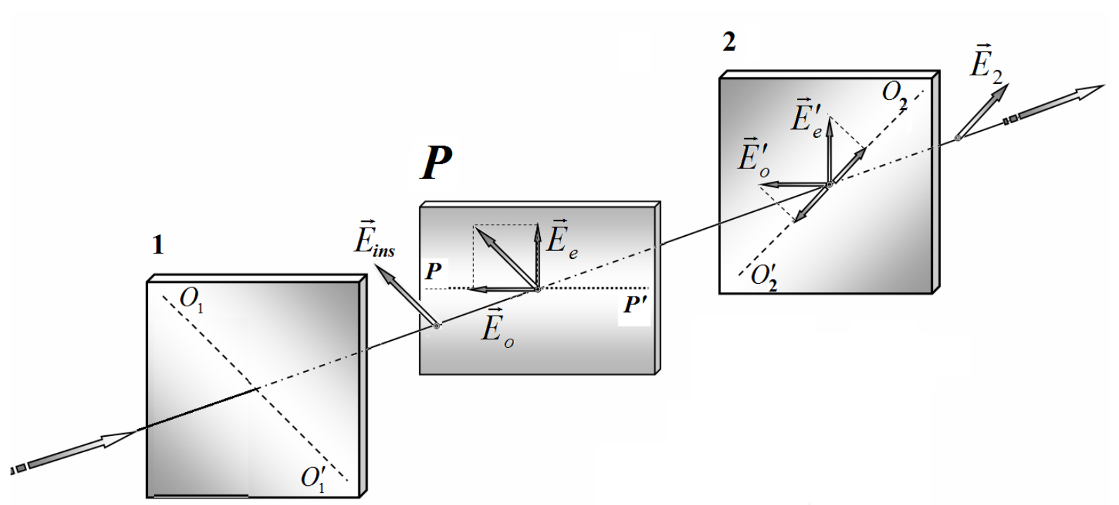
Let a light beam fall onto polarizer 1 whose transmission plane intersects its own plane along the straight line . After passing polarizer 1 the light beam becomes linearly polarized and its electric field strength vector oscillates exactly in the transmission plane of polarizer 1. Then, the light beam falls onto the anisotropic plate oriented such that its optical axis lies in the plate plane to make the angle with the transmission plane of polarizer 1. Two kinds of light waves are then generated in the plate : ordinary , polarized perpendicular to the optical axis of the plate, and extraordinary , polarized along the optical axis of the plate. Refractive indices for these two waves are different and their difference is denoted as . This results in the appearance of the phase difference ( being the plate thickness, being the wavelength of the incident light in vacuum) between the two waves on leaving the plate. Therefore, the polarization of the outgoing light beam changes to be elliptically polarized. The light beam then falls onto polarizer 2, whose transmission plane is perpendicular to the transmission plane of polarizer 1.
A simple derivation shows that the intensity of the light beam transmitted through the plate and polarizer 2 is determined as
where stands for the light intensity falling onto the plate, denotes the light transmittance coefficient of the plate and polarizer 2, and designates the phase difference between the ordinary and extraordinary waves after passing the plate .
In this experiment do not evaluate errors unless asked to do so!
The description of the equipment in Appendix A
Part 1.1.Polarizers (0,8 т.)
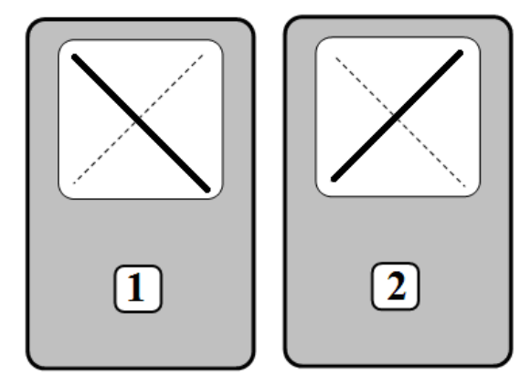
1.1 Find the orientation (i.e. which of the diagonals) of the transmission plane of polarizer 1 and polarizer 2. Show these planes in the figure in the Answer Sheet. (0.8 points) [0,8 т.]
Part 1.2.Rulers (1 т.)
In this part of the experiment use light emitting diodes (LED) as a light source.
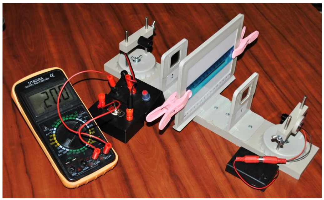
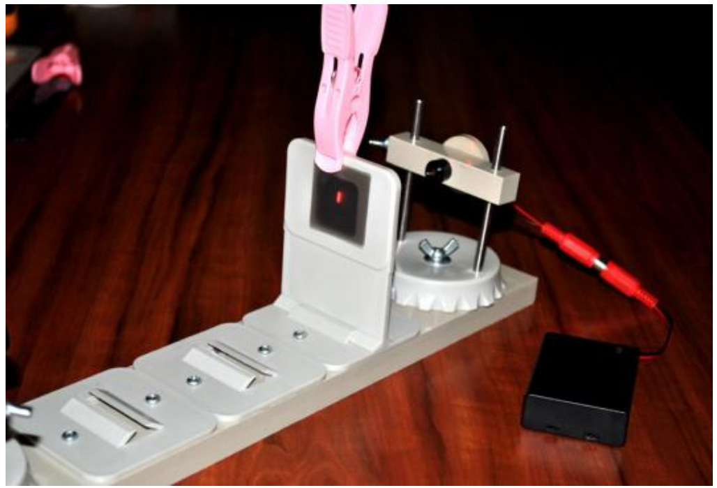
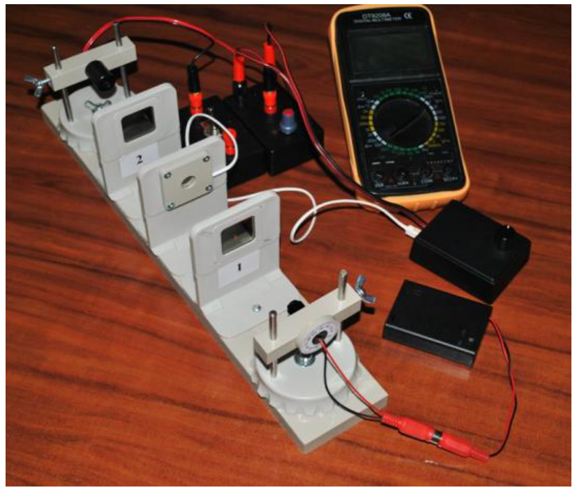
Fix LED on a stand and connect it to its power supply. Set up both polarizers by their face sides (indicated by numbers 1 and 2) pointing towards the light source. Make sure that the polarizers are crossed, i.e. the light beam cannot pass through them. Block the first polarizer by a sheet of white paper placing it on the face side as shown in Fig.1B in Appendix B.
Place the plastic ruler1between the polarizers. You can move the ruler with your hands.
1.2.1 Find the possible directions of the optical axis in the center of the plastic ruler. Show these directions in the figure on the Answer Sheet. (0.4 points) [0,4 т.]
1.2.2 Determine approximately at what distance along the ruler 1 and along the two rulers stacked together, the phase difference for the blue light changes to . (0.6 points) [0,6 т.]
Part 1.3.Strip (0,8 т.)
1.3.1 Find the possible directions of the optical axis of the strip. Show qualitatively them in the figure in the Answer Sheet. (0.4 points) [0,4 т.]
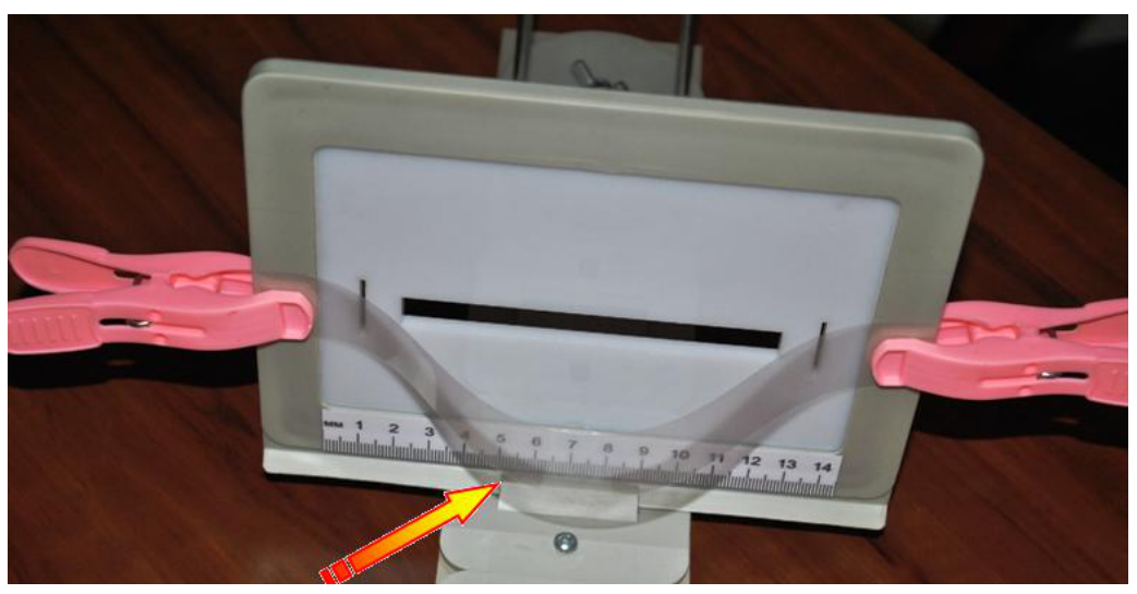
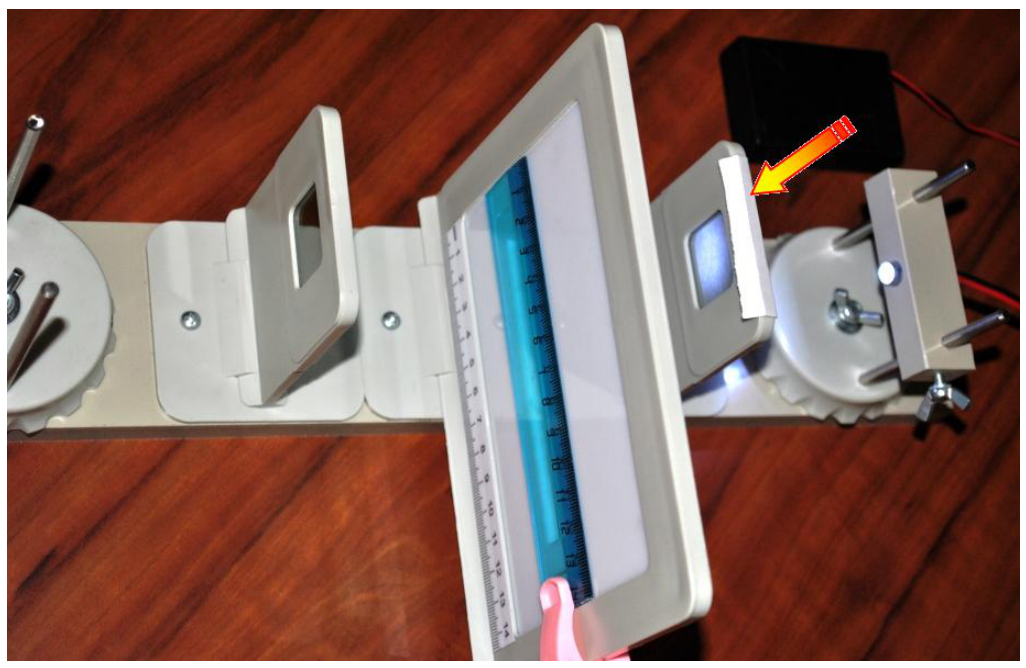
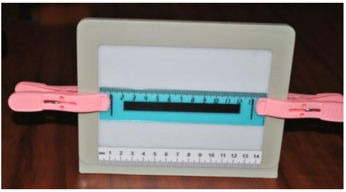
Using the clamps fix a long flexible plastic strip on the screen so that the strip edges coincide with the screenedges. The strip should be curved (see Fig. 3B). Place the screen with the strip between the polarizers. Shifting the screen, observe the color change of the strip. Measure coordinates of strip points on the screen scale, use the left edge of the screen holder as an origin as shown in Figure 3B.
Hereinafter coordinates are measured by the scale in the screen. As a pointer, use the left edge of the holder, which indicated in Fig. 3B by the arrow!
1.3.2 Measure the coordinates of the middle points of two dark bands, the left and the right , visible on the strip. (0.4 points) [0,4 т.]
Part 1.4.Liquid crystal cell (0,9 т.)
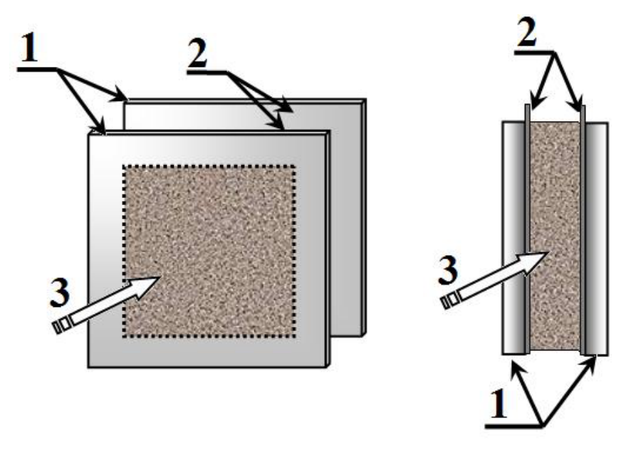
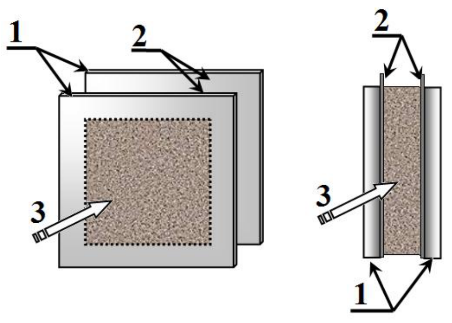
Liquid crystal (LC) is a state of matter that is intermediate between the crystalline solid and the amorphous liquid. The orientation of its molecules can be easily aligned and controlled by applying an electrical field. The LC cell exhibits the optical anisotropy phenomenon with two principal refractive indices. The magnitude of this effect depends on the applied AC voltage. The Liquid Crystal Cell (LCC) is composed of two glass plates 1 whose inner surface is coated with a transparent conductive layer 2. Between the plates there is a thin (approximately 10 microns) layer of the solution 3 which is in a liquid crystal state. Leads are soldered to the plates for connecting to the AC power supply.
Place the liquid crystal cell (LCC) between the polarizers. Plug it into its power supply. Varying the voltage across the LCC observe the changing colors of the light transmitted through it.
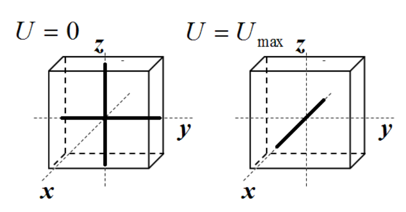
1.4.1 Find the possible directions of the optical axis of the LCC at zero and maximum voltage applied across it. Show these directions in the figure on the Answer Sheet. -axis is directed vertically. (0.6 points) [0,6 т.]
1.4.2 Measure the voltage across the cell at which abrupt, with respect to voltage, reorientation of liquid crystal molecules by occur. Make sure that multimeter is on AC voltage mode. (0.3 points). [0,3 т.]
Appendix A. Experimental equipment
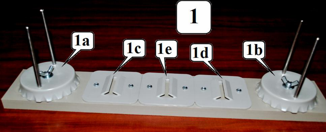
Optical bench 1with holders:
1a – support for the light source with the screw;
1b – support for the photodetector with the screw;
1c, 1d – stands for the polarizers;
1e – stand for the screen and the liquid crystal cell (LCC).
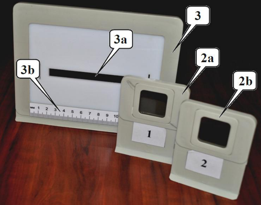
2a, 2b – polarizers on the stands. There are numbers 1 and 2 on their face sides.
The polarizers should be installed with their face sides towards the light source!
The transmission planes of the polarizers makes the angle with the horizontal.
3 – the screen with the slit (3a) and the scale (3b)
Light sources:
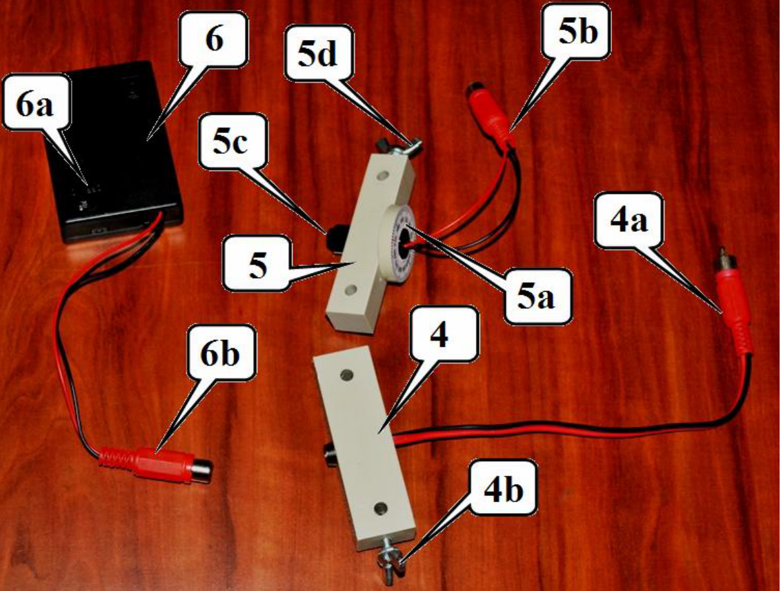
4 – light emitting diode (LED):
4a – leads for the power supply;
4b – fixing screw;
5 – laser:
5a – ring for turning the laser with the scale (scale is not used);
5b – leads for the power supply;
5c – the screw for the beam width adjustment on the front side;
5d – fixing screw;
6 – power supply for light sources:
6a – switch;
6b – leads for light source.
Keep the source operating only while making measurements!
Do not point the laser beam in your or anyone’s eyes, it is very dangerous!
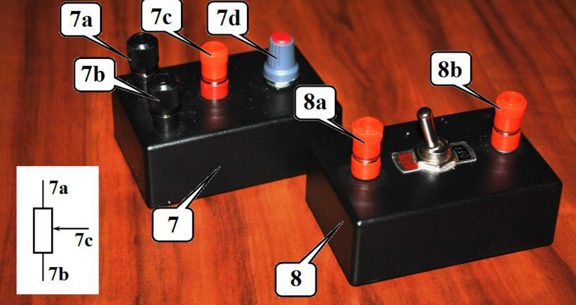
7 – variable resistor:
7a, 7b, 7c – terminals for connection to a circuit
7d – knob for changing resistance.
8 – switch:
8a, 8b – terminals for connection to a circuit;
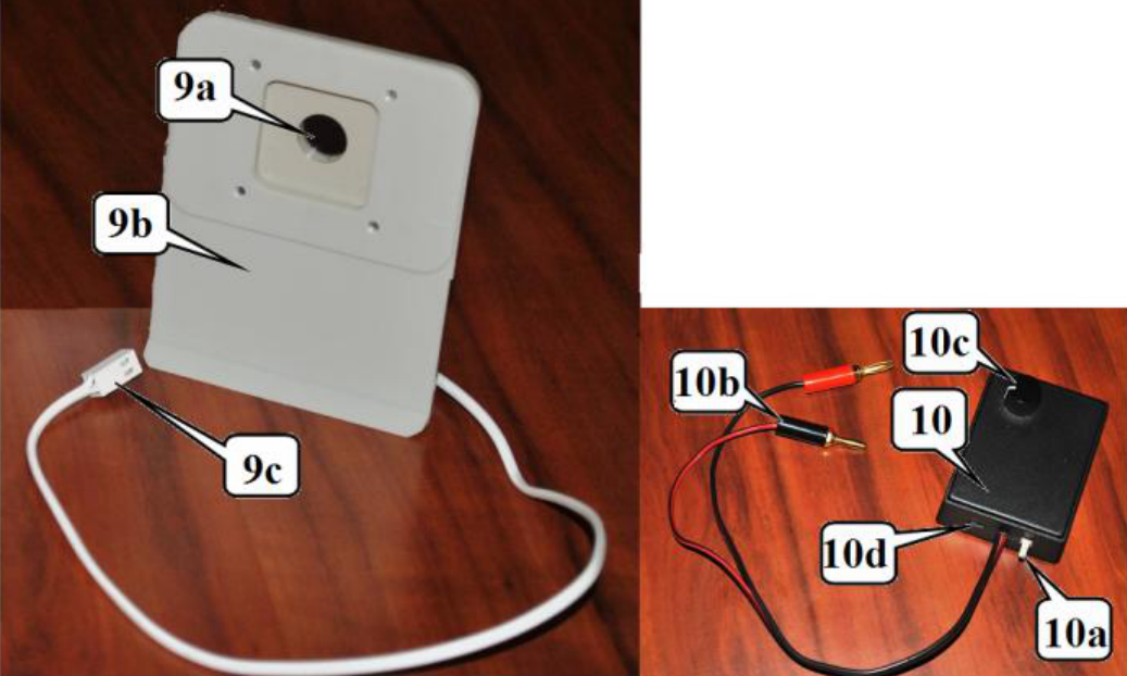
9a – liquid crystal cell (LCC) 9ain a holder (9b), 9c – lead for connecting to the power supply;
10 – the power supply for LCC:
10a – connector for the LCC;
10b – leads for measuring the output voltage;
10c – knob to adjust the output voltage;
10d – power on/off.
Keep the source operating only while making measurements!
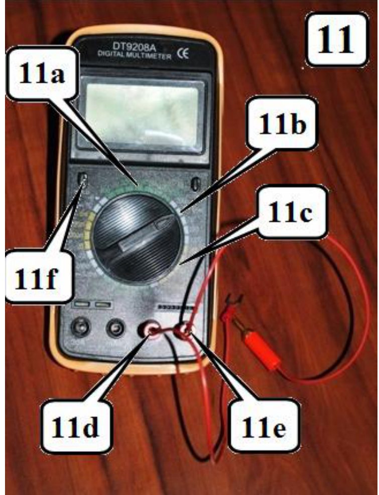
11 – multimeter;
Do not press the HOLD button
11a – register to measure resistance (200 kOhm);
11b – register to measure DC voltage (2V);
11c – register to measure AC voltage (20V);
11d, 11e – connectors for test leads;
11f –power on/off.
If the display multimeter is in a "sleep" mode - double-press power on/off!
When measuring the resistance with the multimeter, the element must be disconnected with a power supply!
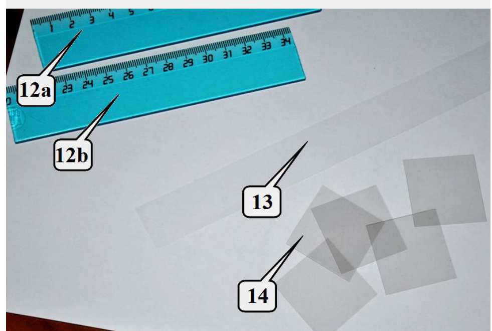
Optical elements to be investigated
12 – plastic rulers:
12a –No. 1 (with the scale from 0 to 14 cm)
12b –No. 2 (with the scale from20 to34cm)
13 – flexible strip;
14 – set of identical filters;
The filters and the strip are provided in a separate envelope!
The plastic rulers and the strip exhibit birefringence, their optical axes lie in their own planes.
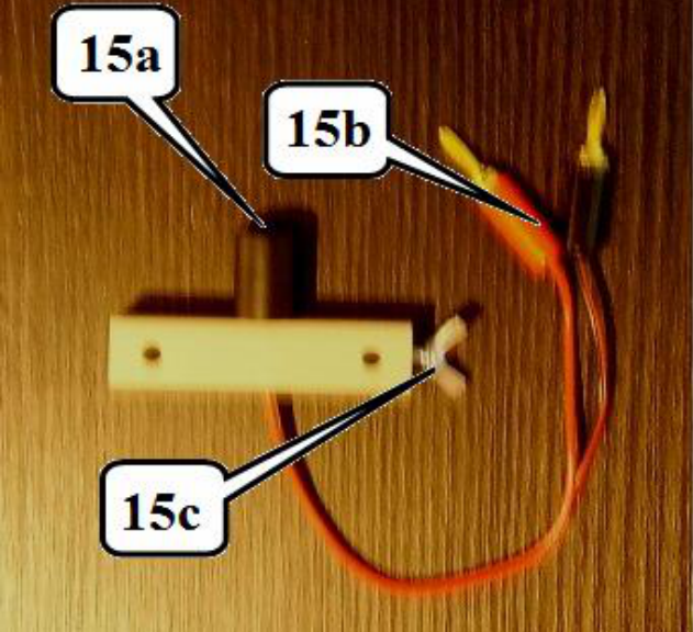
15 Photodetector (photodiode)
15a - input window;
15b - leads for measuring the output voltage;
15c –fixing screw.
Connecting wires, clamps, paper napkin, a piece of paper.
The liquid crystal cell is composed of two glass plates 1 whose inner surface is coated with a transparent conductive layer 2. Between the plates there is a thin (approximately 10 microns) layer of the solution 3 which is in a liquid crystal state. Leads are soldered to the plates for connecting to the AC power supply. In the absence of voltage long molecules of liquid crystal are oriented parallel to the plates. The direction of molecular orientation coincides with the optical axis of the crystal.
Try not to touch those parts of the optical elements through which the light passes! If necessary, wipe them with a paper napkin!
Appendix B. Photos of the experimental setups
Отговори
Part 1.2.Rulers, 1.2.2 ~12 cm for the ruler No.1; ~ 8 cm for the two rulers stacked together
Part 1.3.Strip, 1.3.2 xL = 3,5 cm, xR = 7,5 cm
Part 1.4.Liquid crystal cell, 1.4.2 2 V
Approximate value from the official solution: Ucr = 2 V.
Решение
Experimental problem. To see invisible!
Part 1. Qualitative observations!
Section 1.1. Polarizers
For determination of the transmission plane of the polarizer, one can use a glaring effect from any shining surface. It is known that the reflected light is polarized in the plane of the reflecting surface. The corresponding transmission planes are shown in the figure on the right.
Section 1.2. Rulers
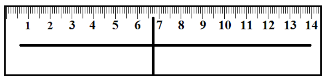
1.2.1. In case of the incident light being polarized along the optical axis or perpendicular to it, there is only one kind of waves generated in the medium. This means that no change in light polarization is to occur. Thus, it is possible to determine either the direction of the optical axis or the direction which is perpendicular to it. Those possible alternatives are shown in the figure above (either along the ruler, or perpendicular to it).
1.2.2. One can see at what parts of the rulers similar colors are observed, mainly with blue hue.
The distance between those bands for the ruler No.1 is ~12 cm, while for the two rules stacked together it is ~ 8 cm.
Section 1.3. Strip
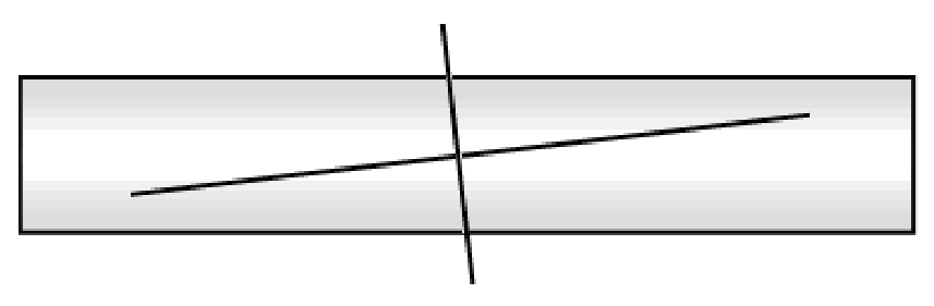
1.3.1 Possible directions of the optical axis of the strip can be determined in a similar way. As shown in the figure on the right, those directions make a small angle with the sides of the strip.
1.3.2 The coordinates of the dark bands are approximately found as follows , .
Section 1.4. Liquid crystal cell
1.4.1 In case of zero voltage, the directions of the optical axis can be determined in the same way: It is either horizontal or vertical. At the maximum voltage applied the optical axis orients along the electric field, which means it turns perpendicular to the cell plane.
1.4.2 The voltage at which such a sharp transition in orientation of molecules of the liquid crystal occurs is approximately equal to
Оригинал в Архива: 2014_IPhO_Experimenta_Competition.pdf · официални решения: 2014_IPhO_Solution_to_Experimental_Competition.pdf