IPhO 2019, Теория — Задача 2.1. The structure and operation of a magnetron
The Physics of a Microwave Oven · 6,6 т.
The Physics of a Microwave Oven
This question discusses the generation of microwave radiation in a microwave oven, and its use to heat up food. The microwave radiation is generated in a device called “magnetron”. Part A concerns the operation of the magnetron, while part B deals with the absorption of microwave radiation in food.
Условие
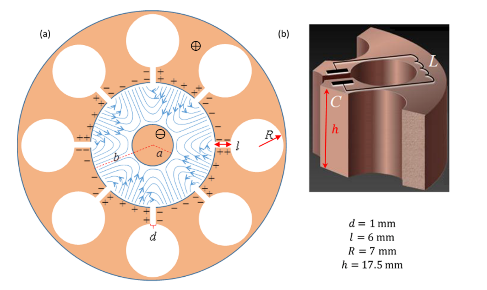
A magnetron is a device for the generation of microwave radiation, either in pulses (for radar applications), or continuously (e.g., in a microwave oven). The magnetron has a mode of self-amplifying oscillations. Supplying the magnetron with static (non-alternating) voltage quickly excites this mode. The microwave radiation thus created is transmitted out of the magnetron.
A typical microwave oven magnetron consists of a solid copper cylindrical cathode (with radius ) and a surrounding anode (with radius ). The latter has the shape of a thick cylindrical shell into which cylindrical cavities are drilled. These cavities are known as “resonators”. One of the resonators is coupled to an antenna which will transmit the microwave energy out; we will ignore the antenna in the following. All internal spaces are in vacuum. We will consider a typical magnetron with eight resonators, as depicted in Figure 1(a). The three-dimensional structure of a single resonator is shown in Figure 1(b). As indicated there, each of the eight cavities behaves as an inductor-capacitor (LC) resonator, with operating frequency .
A static uniform magnetic field is applied along the magnetron's longitudinal axis, pointing out of the page in Figure 1(a). In addition, a constant voltage is applied between the anode (positive potential) and the cathode (negative potential). Electrons emitted from the cathode reach the anode and charge it, such that they excite an oscillation mode in which the sign of the charge is opposite between every two adjacent resonators. The oscillation of the cavities amplify these oscillations.
The process described above creates an alternating electric field with the aforementioned frequency (blue lines in Figure 1(a); the static field is not plotted) in the space between the cathode and the anode, in addition to the static field caused by the applied constant voltage. In the steady state, the typical amplitude of the alternating electric field between the anode and the cathode is approximately of the static electric field there. The electron motion in the space between the cathode and the anode is affected by both the static and the alternating parts of the field. This causes electrons that reach the anode to transfer about of the energy they acquire from the static field into the alternating field. A minority of the ejected electrons returns to the cathode and releases additional electrons, further amplifying the alternating field.
Each resonator can be thought of as a capacitor and an inductor, see Figure 1(b). The capacitance mainly arises from the planar parts of the resonator surface, while the inductance stems from the cylindrical part. Assume that the current in the resonator flows uniformly very close to the surface of its cylindrical cavity, and that the strength of the magnetic field generated by this current is times that of an ideal infinite solenoid. The various lengths defining the resonator geometry are given in Figure 1(b). The vacuum permittivity and permeability are and , respectively.
A.1 Use the above data to estimate the frequency of a single resonator. (Your result may differ from the actual value, . Use the actual value in the remainder of the question.) [0,4 т.]
Task A.2 below does not deal with the magnetron itself, but helps to introduce some of the relevant physics. Consider an electron moving in free space under the influence of a uniform electric field directed along the negative axis, , and a uniform magnetic field directed along the positive axis, ( and are positive; are unit vectors oriented in the conventional manner). Let us denote the electron velocity at time by . The drift velocity of the electron is defined as its average velocity. We denote by and the mass and charge of the electron, respectively.
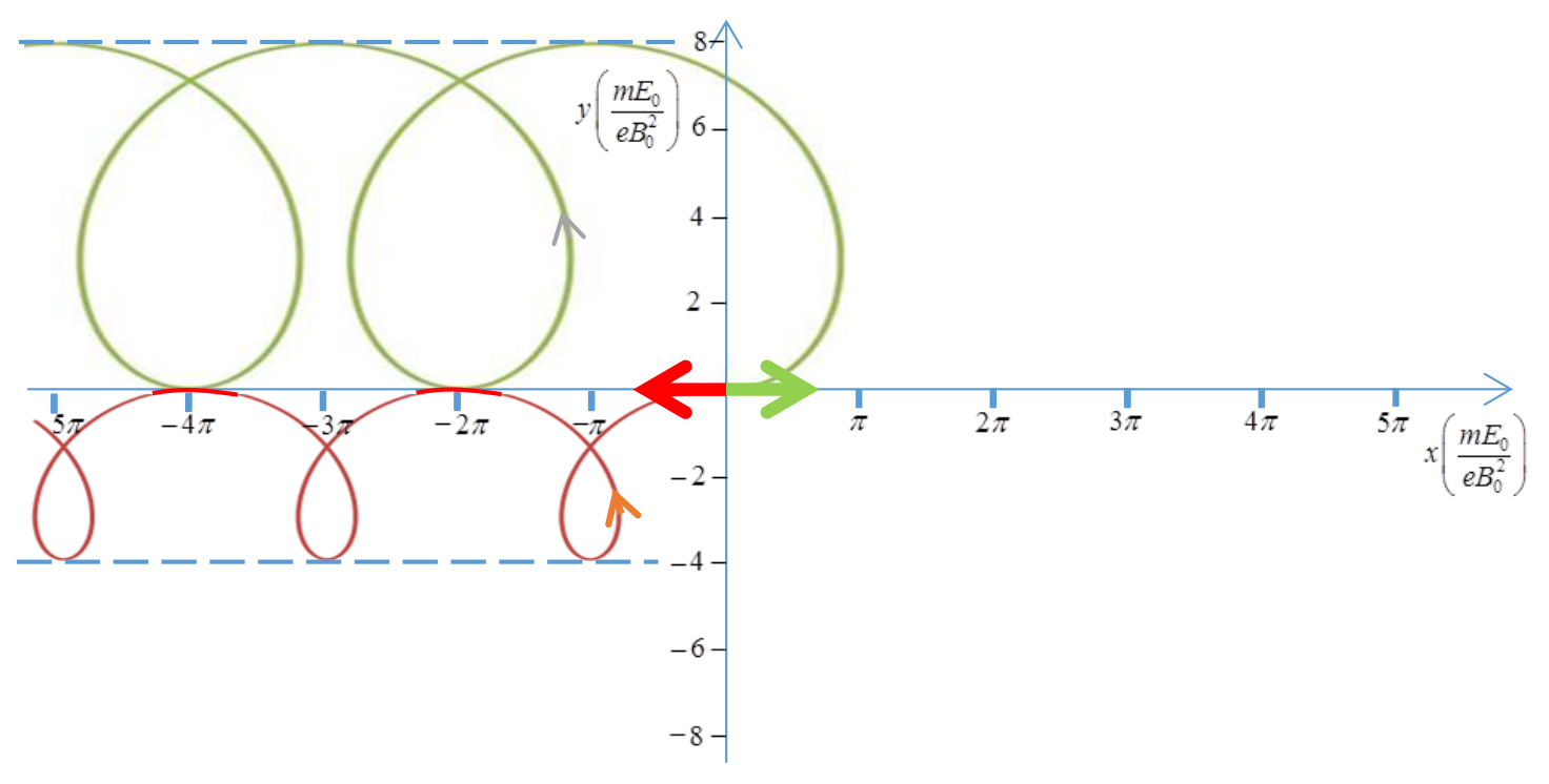
A.2 In each of the following two cases, find . In addition, draw in the Answer Sheet the electron's trajectory (in the lab frame) during the time interval if:
- at the electron velocity is ,
- at the electron velocity is . [1,5 т.]
We now resume our discussion of the magnetron. The distance between the cathode and the anode is . Assume that, due to the aforementioned energy loss to the alternating fields, the maximal kinetic energy of each electron does not exceed . The static magnetic field strength is . The electron mass and charge are and , respectively.
A.3 Numerically estimate the maximal radius of the electron motion trajectory in the reference frame in which this motion is approximately circular, considering this reference frame as approximately inertial. [0,4 т.]
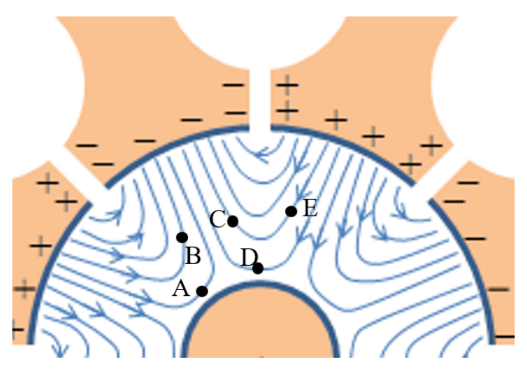
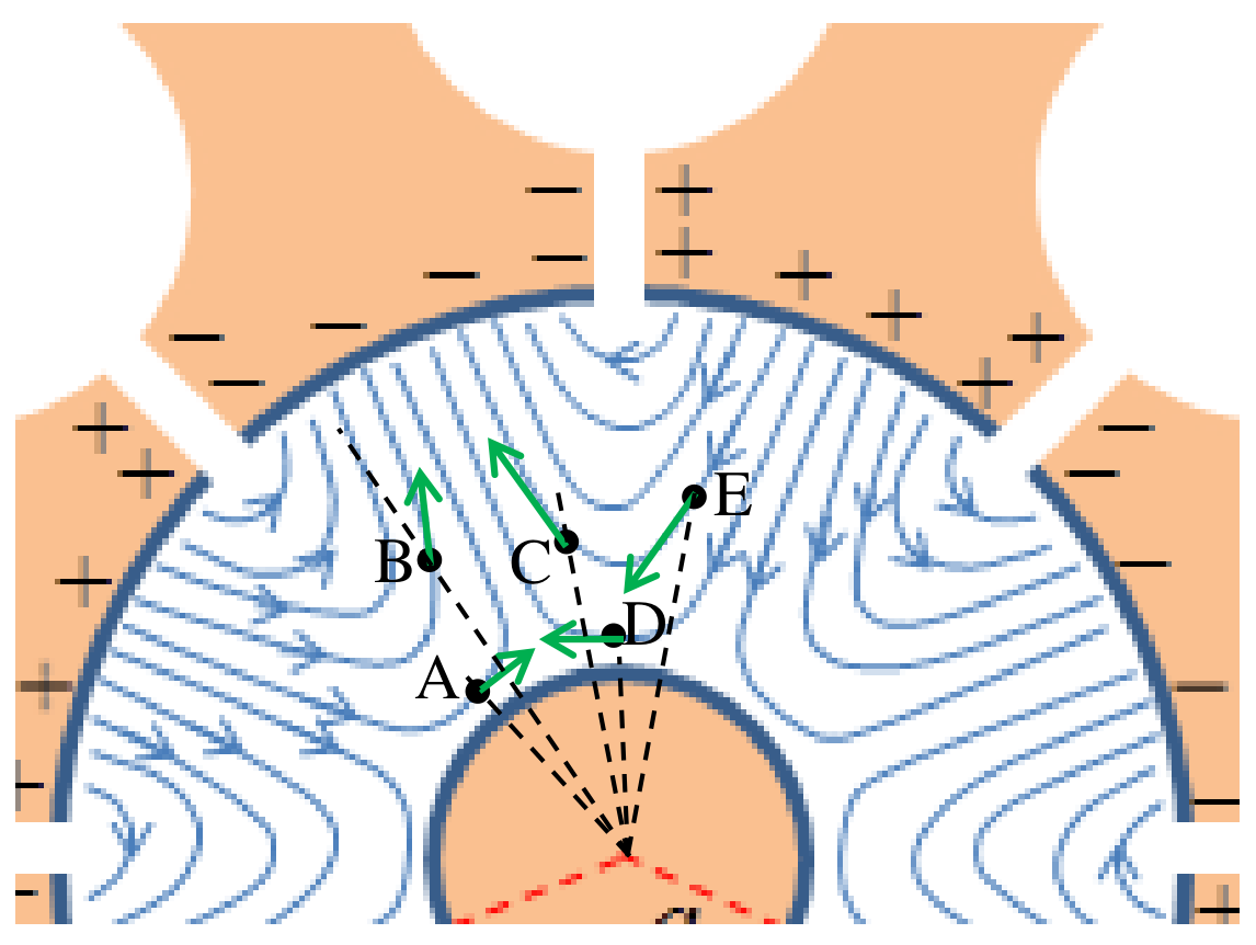
A.4 Figure 2 depicts the alternating electric field lines between the anode and the cathode at a given moment in time (the static field is not plotted). Indicate in the Answer Sheet which of the electrons positioned at A,B,C,D and E will drift towards the anode, which will drift towards the cathode and which will drift at a direction perpendicular to the radius at that moment. [1,2 т.]
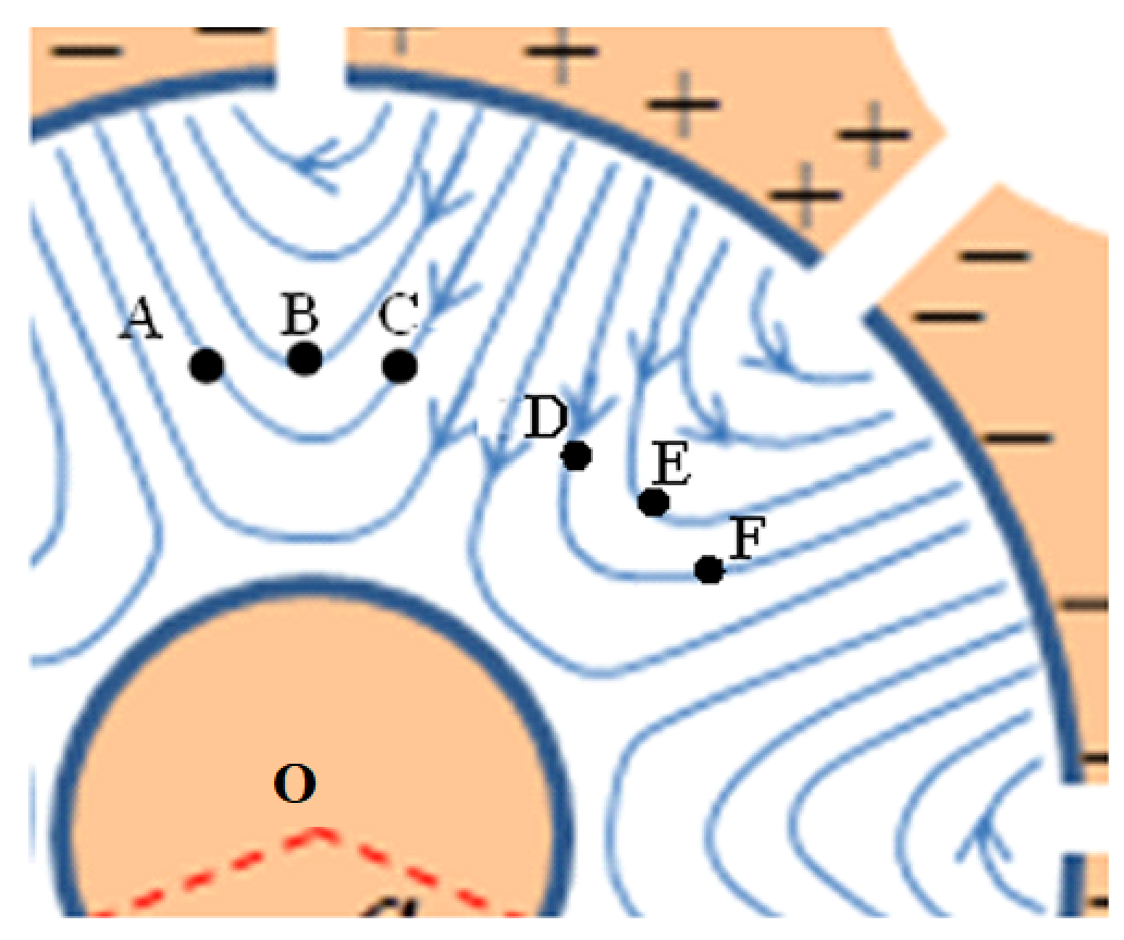
Figure 3 depicts the alternating electric field lines between the anode and the cathode (the static field is not plotted) at a given moment in time. The positions of six electrons at that moment are denoted by A, B, C, D, E and F. All electrons are at the same distance from the cathode.
A.5 Consider the situation shown in Figure 3. For each of the six electron pairs AB, AC, BC, DE, DF, EF, indicate in the Answer Sheet whether their drift will cause the angle between their position vectors (measured from the cathode’s center O) to increase or decrease at that moment. [1,2 т.]
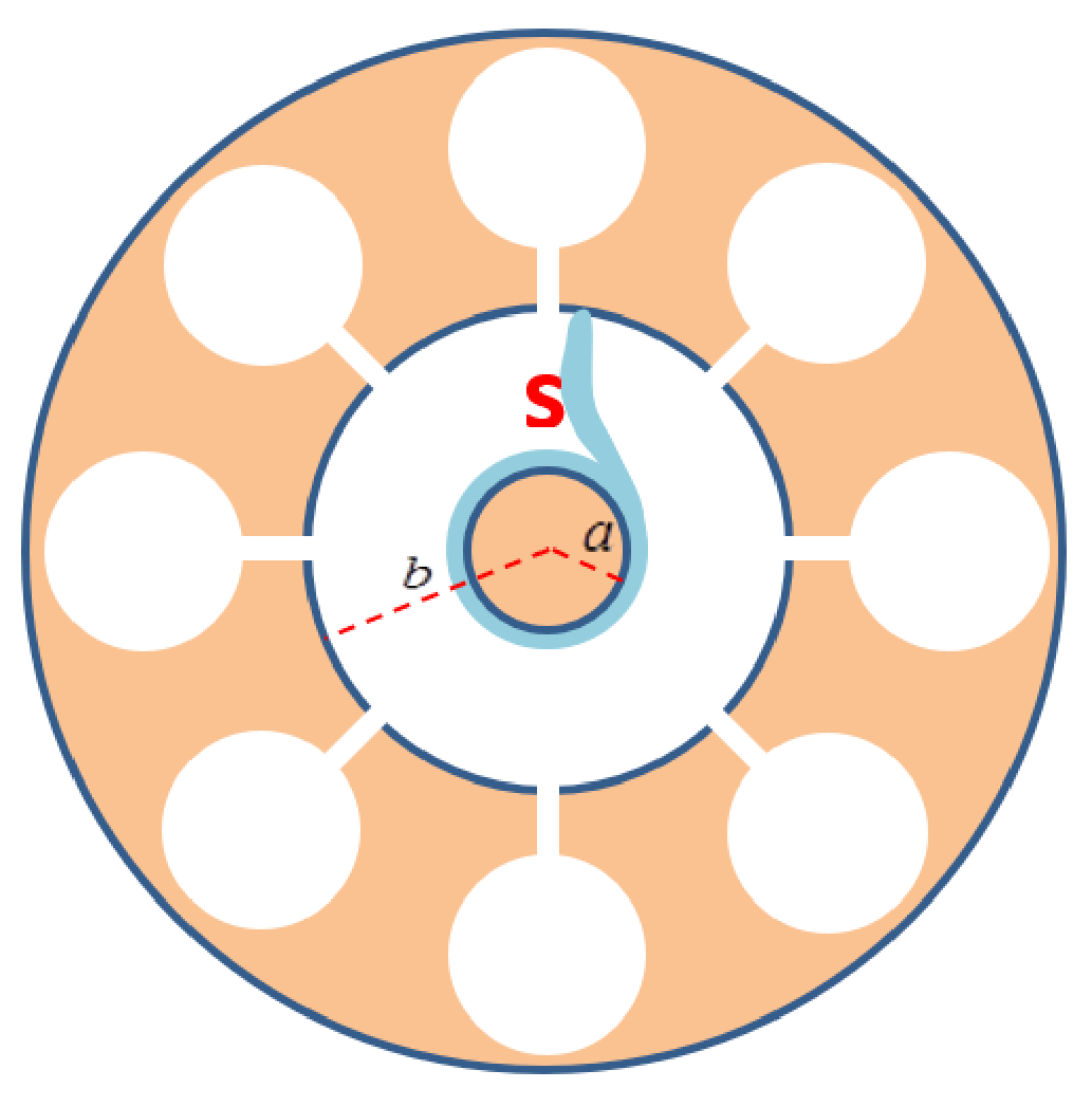
The pattern you have discovered in Task A.5 acts as a focusing mechanism, concentrating the electrons in the space between the cathode and anode into spokes. Figure 4 depicts one such spoke, denoted by S.
A.6 Depict in the Answer Sheet the other spokes at that moment. Indicate by arrows their direction of rotation, and calculate their average angular velocity . [0,8 т.]
Make the approximation that the total electric field half-way between the cathode and the anode is equal to its average static value along a radial line from the cathode to the anode, and that the spokes are approximately radial in that region. The cathode and anode radii ( and , respectively) are defined in Figure 4.
A.7 Find an approximate expression for the static voltage required for operating the magnetron in the manner described. (The expression you will find gives an approximation for the minimal value required for the magnetron operation; the optimal voltage is somewhat higher.) [1,1 т.]
Отговори
A.1 Hz
A.2
In both cases; case 1: , ; case 2: , .
A.3 0.000318 m
A.4 A and B drift towards the cathode; C, D and E drift towards the anode.
A.5 AB, AC, BC: angle decreases; DE, DF, EF: angle increases.
A.6 rad/s
Four spokes rotating counterclockwise; .
A.7
Решение
The Physics of a Microwave Oven – Solution
Part A: The structure and operation of a magnetron
A.1. The frequency of an LC circuit is . If the total electric current flowing along the boundary of the cavity is , it generates a magnetic field whose magnitude (by the assumptions of the question) is , and a total magnetic flux equal to , hence the inductance of the resonator is . Approximating the capacitor as a plate capacitor, its capacitance is . Putting everything together, we find
A.2. Denoting the electron velocity by , in this case the total force applied on it is
Let us write , with being the drift velocity of a charged particle in the crossed electric and magnetic fields (the velocity at which the electric and magnetic forces cancel each other exactly). Then . Thus, in a frame moving at the drift velocity , the electron trajectory is a circle with constant-magnitude velocity , and radius . In the lab frame this circular motion is superimposed upon the drift at the constant velocity . Hence:
- For we find and .
- For we find and .
This information, together with the independence of the period of the circular motion on allows us to plot the electron trajectory in both cases (green and red, for cases 1 and 2, respectively):
A.3. The velocity of the electron in a frame of reference where the motion is approximately circular is . From A.2 we get that and , hence .
The radius of the circular motion of the electron in this frame is . The maximal velocity is that corresponding to a kinetic energy, , of 800 eV.
Substituting we find .
Since this maximal radius is much smaller than the distance between the anode and the cathode, we may ignore the circular component of the electronic motion, and approximate it as pure drift.
A.4. As just explained, we may approximate the electron motion as pure drift. In task A.2 we have found that the direction of the drift velocity is in the direction of the vector . Since we are interested in radial component of the drift velocity, the only contribution is from the azimuthal component of the electric field. The static electric field has no azimuthal component, hence the drift in the radial direction results solely from the azimuthal component of the alternating electric field. What we have to check is if the azimuthal component points clockwise or counterclockwise. From the direction of the field lines it is easy to see (attached figure) that in points A and B the azimuthal component pointing clockwise therefore the electrons there drift towards the cathode, while for points C, D and E the azimuthal component points counterclockwise and the electrons there drift toward the anode.
| Point | toward the anode | toward the cathode | perpendicular to the radius |
|---|---|---|---|
| A | X | ||
| B | X | ||
| C | X | ||
| D | X | ||
| E | X |
A.5. In this task we need to consider the azimuthal component of the drift velocity, which results from the radial component of the electric field. Since all points are at the same distance from the anode, all electrons experience the same static electric field. Hence only the radial component of the alternating field determines whether the angle between the electrons’ position vectors would increase or decrease: If the radial component of the alternating field points inwards (towards the cathode), the azimuthal drift velocity will be positive (counterclockwise) and vice versa. Hence the electrons at A, B and C drift closer to each other in terms of angles, while those at D, E and F drift away from each other.
| points | angle decreases | angle increases | indeterminate |
|---|---|---|---|
| AB | X | ||
| BC | X | ||
| CA | X | ||
| DE | X | ||
| EF | X | ||
| DF | X |
A.6. Spokes will be created only in the regions where focusing occurs. By the result of the previous task, there are four spokes, as indicated in the attached Figure.
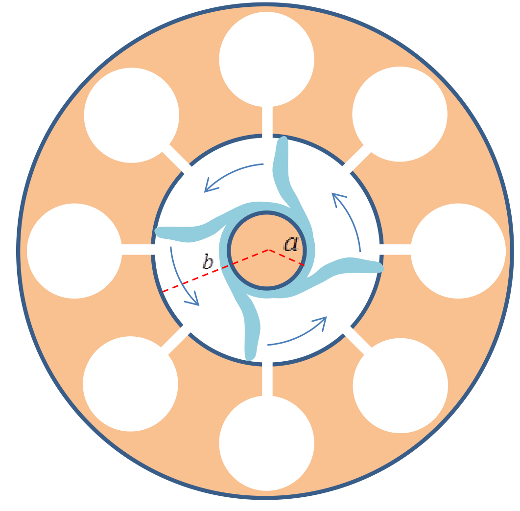
The electron drift sets the spokes in a counterclockwise rotation. The frequency of the alternating field is GHz. By the time the alternating field flipped its sign (half a period), each spoke moves to the next cavity, corresponding to an angle of . Therefore, the angular velocity of each spoke is
. Each spoke performs a full rotation around the magnetron after four periods of the alternating field.
A.7. The magnitude of the electric field in the region considered, , is the magnitude of the static field, that is, , giving rise to an azimuthal drift velocity of magnitude . Equating with the angular velocity found in the previous task we find