IZhO 2010, Експеримент — Задача 1. Slow motion
VI International Zhautykov Olimpiad — EXPERIMENTAL COMPETITION — 14 January, 2010
Please read the instructions first:
The Experimental part consists of one problem. This part of the competition lasts 3 hours.
Please only use the pen that will be given to you.
You can use your own non-programmable calculator for numerical calculations. If you don’t have one, please ask for it from Olympiad organizers.
You are provided with Writing sheet and additional papers. You can use the additional paper for drafts of your solutions but these papers will not be checked. Your final solutions which will be evaluated should be on the Writing sheets. Please use as little text as possible. You should mostly use equations, numbers, figures and plots.
Use only the front side of Writing sheets. Write only inside the bordered area.
Begin each question on a separate sheet.
Write on the blank writing sheets whatever you consider is required for the solution of the question.
Fill the boxes at the top of each sheet of paper with your country (Country**), your student code (Student Code), the question number (Question Number)**, the progressive number of each sheet (Page Number), and the total number of Writing sheets (Total Number of Pages). If you use some blank Writing sheets for notes that you do not wish to be evaluated, put a large X across the entire sheet and do not include it in your numbering.
At the end of the exam, arrange all sheets for each problem in the following order:
- Used Writing sheets in order;
- The sheets you do not wish to be evaluated
- Unused sheets and the printed question.
Place the papers inside the envelope and leave everything on your desk. You are not allowed to take any paper or equipment out of the room
Условие
The aim of this work is to study the motion of bodies in a viscous medium.
Equipment List:
- Tripod
- Ruler of 30 cm
- Stopwatch
- Disposable syringes 10 ml
- Liquid Gel (liquid soap) - 20 ml
- Glass tube with the inner diameter – D=4.6 mm
- Wooden sticks (diameter 3 mm)
- A set of metal rods, length 4 cm, diameters d= 2.5; 3.0; 3.5; 4.0 mm
- Disposable glass
- Napkins to wipe the table and hands
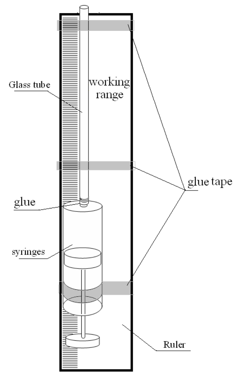
Apparatus
In this experiment use the following installation. The glass tube is glued to the tip of the syringe. Tube with a syringe is attached to the ruler with an adhesive tape. Using the syringe you can fill up the tube with the gel. This setup can be fixed to the tripod vertically, either with the tube pointing upward or downward. Inside the tube you can place metal or wooden rods, the motion of which you will explore.
For successful completion of the experiment, strictly follow the instructions below:
- Make sure that the tube is completely filled with the gel and there are no air bubbles inside it;
- Change the gel in the syringe and the tube only when necessary;
- Once you put a metal rod (or wooden stick) in the receiver, wait until it starts to move steadily, for this it must travel a distance of about 4-5 cm;
- The results of measurements of the characteristics of motion have significant dispersion, so all measurements should be conducted several times;
- Be careful of the sharp edge of the tube!
Part 1. Metal
Place the tube vertically with the open end pointing upward, so that you could put the metal rods into the tube. If necessary, conduct a second experiment, simply overturning the tube: when the rod sinks down, turn the tube upside down and you can repeat the measurement.
1.1 Prove experimentally that the motion of the rod inside the tube is uniform. Use only metal rod of diameter of 4.0 mm in this case.
Determine the velocity of the rod sinking in the gel as accurately as possible. Calculate the error of the velocity measured.
1.2 Measure the dependence of the velocity of the rods (with the same length) on their diameters. Plot a graph of the obtained dependence.
1.3 Theoretically, we can show that the velocity of the rod depends on the thickness of the gap between the tube walls and the lateral surface of the rod (if the gap is small compared to the radius of the tube) according to the law
where is a constant.
Using your experimental data, check whether this dependence holds.
1.4 Determine the power index in formula (1) which most accurately fits the experimental data. Make error estimation of the obtained value of this power index .
1.5 Give a brief theoretical justification for the result obtained in Question 4.
Part 2. Wood
Overturn the syringe with the tube pointing downward. Insert a wooden rod into the tube (from below) then it will slowly emerge. You have to study the motion of the wooden rod. The wooden rod should be completely immersed in the fluid when it moves.
2.1 Prove experimentally that the motion of the rod inside the tube is uniform.
Measure the velocity of the rod in the gel as accurately as possible. Make error estimation of the obtained value of the velocity.
To conduct this experiment, use stick of maximal length.
2.2 Investigate a dependence of rod velocity on its length. Plot a graph of the obtained dependence. Make error estimation of the obtained values.
2.3 Give a brief theoretical explanation of the result obtained in Question 2.
Отговори
1.1 0.14 cm/s
Official solution: V = (0,140 ± 0,001) sm/s (printed “sm” for cm).
1.4 3.11
Official solution: γ = 3,11 ± 0,16 (least-squares slope of ln V versus ln(D−d)).
2.1 0.0825 cm/s
Official solution: V = (0,0825 ± 0,0004) cm/c (printed “cm/c”).
2.2 The emerging velocity does not depend on the stick length: V = (0,08 ± 0,01) sm/s; the plot is a horizontal straight line.
Printed “sm/s” for cm/s.
Решение
Experimental competition
Solution
Part 1.
- It is necessary to obtain the motion law of the rod. In this experiment it is preferable to measure time intervals at which the rod passes preliminary fixed paths, say 1 sm. Table 1 shows the corresponding measurements and Fig.1 graphically demonstrates the same dependence.
Table 1.
| x, sm | t, s |
|---|---|
| 0 | 0 |
| 1 | 6,9 |
| 2 | 14,3 |
| 3 | 21,8 |
| 4 | 29,2 |
| 5 | 36,8 |
| 6 | 44,1 |
| 7 | 51,0 |
| 8 | 58,4 |
| 9 | 65,7 |
| 10 | 72,2 |
| 11 | 79,0 |
| 12 | 85,9 |
| 13 | 92,9 |
| 14 | 100,3 |
| 15 | 107,7 |
| 16 | 114,6 |
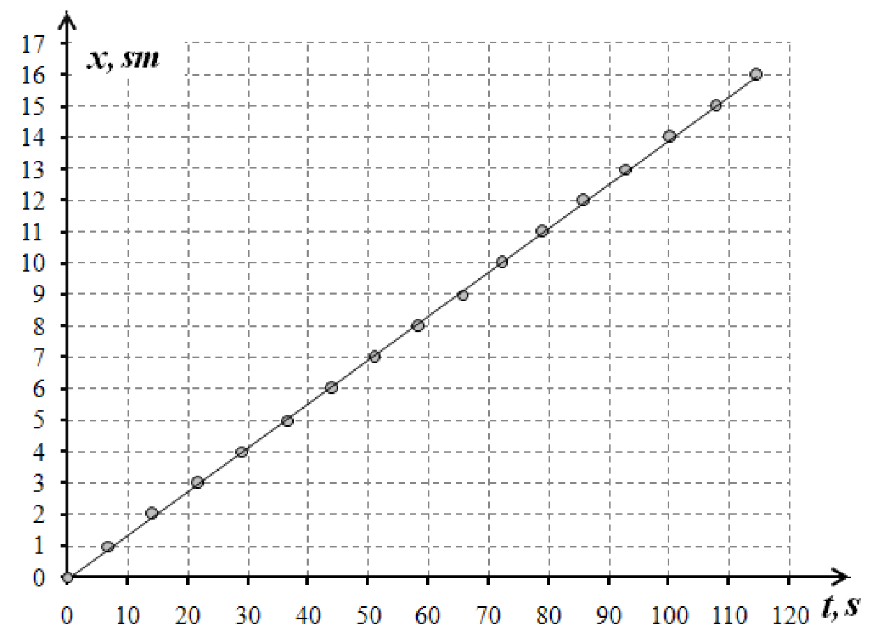
The experimental line in Fig. 1 is linear with high accuracy which proves that the rod really moves uniformly. The most accurate technique of determining average velocity of the rod is least-squares method. The slope of the straight line in Fig.1 gives an average velocity which in this particular case is
- In this part of the experiment it is necessary to measure the rod velocity several times and to guarantee maximal accuracy the fixed path for the rod to pass should be over 10 sm. Table 2 presents the measurement results for the time intervals t for the rods of different diameters and the calculated velocities V.
Table 2.
| d, mm | x, sm | t₁,s | t₂,s | t₃,s | , s | Δt, s | V, sm/s | ΔV, sm/s |
|---|---|---|---|---|---|---|---|---|
| 4,0 | 10 | 77,5 | 76,6 | 81,7 | 78,60 | 5,4 | 0,13 | 0,01 |
| 3,5 | 10 | 11,7 | 11,6 | 12,0 | 11,76 | 0,48 | 0,85 | 0,03 |
| 3,0 | 10 | 3,4 | 3,3 | 3,3 | 3,35 | 0,12 | 2,99 | 0,11 |
| 2,5 | 20 | 3,3 | 3,5 | 3,2 | 3,33 | 0,30 | 6,01 | 0,54 |
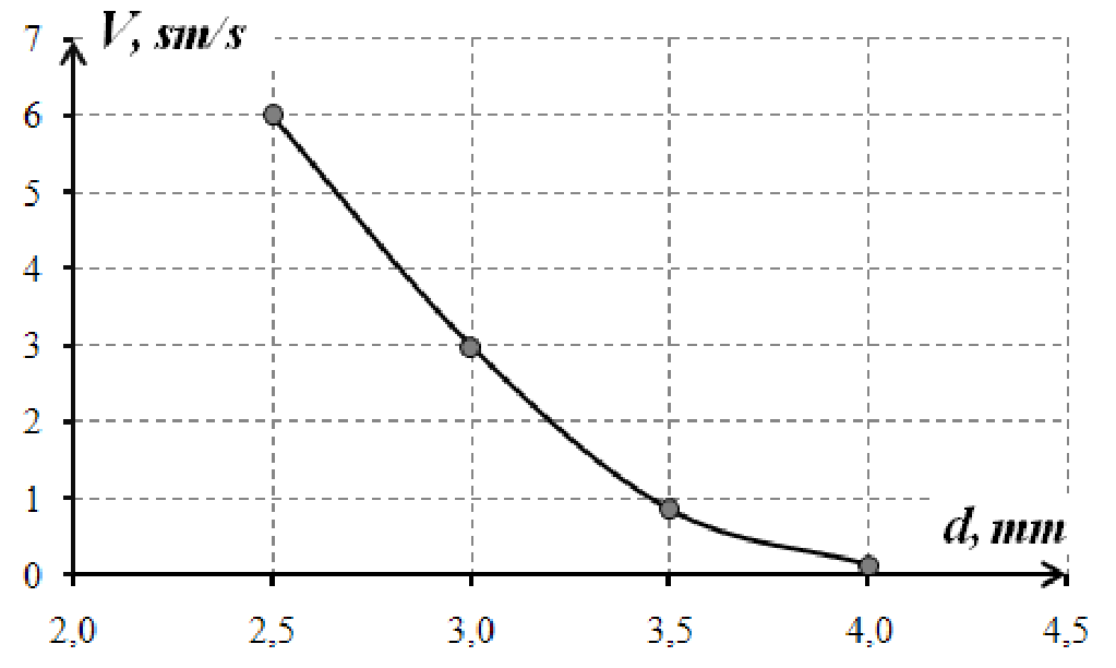
To calculate the average velocity the following formula is used
where is the average of the measured time intervals.
The experimental error can be evaluated as
The corresponding dependence is plotted in Fig.2.
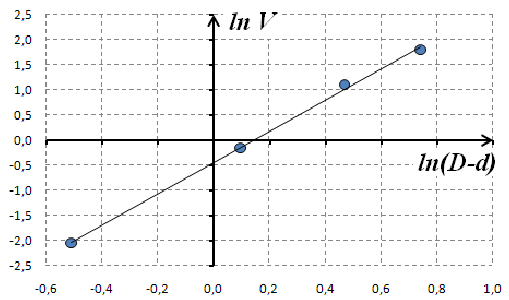
- To check the validity of the formula written in the experimental task it is necessary to plot in logarithmic scale the average velocity dependence on the difference between the diameters of the test tube and the rod. It is done in Fig.3.
The linearity of the obtained line clearly demonstrates the power dependence between the chosen values, i.e. proves the validity of formula (1) written in the experimental task// It is possible that the last point in Fig.3 deviates slightly from the straight line due to the big gap between the rod and the test tube walls.
- The power index in formula (1) is numerically equal to the slope of the straight line in Fig.3. Calculation with the least-squares method gives rise to the following value
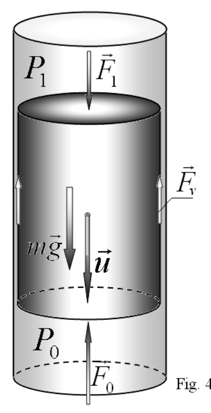
- When the rod sinks the liquid has to flow between the lateral surface of the rod and the test tube walls (Fig.4). To overcome the viscous friction of the liquid, the pressure difference should appear between the lower and upper ends of the rod. It is this difference in the pressure that produces an additional force acting on the sinking rod. Besides, the rod is slowed down by the above mentioned viscous friction acting on its lateral surface.
It is reasonable to assume that the viscous friction force acting on the liquid in the gap from the tube walls is proportional to the average velocity of the flowing liquid and inversely proportional to the gap size.
At uniform flowing of the liquid this force is compensated by the pressure difference (the weight of the liquid in the gap is negligible due to the small size of the gap)
where is the area of the transversal section of the gap. Since the rod moves slowly, one can neglect the viscous friction and write
where is the area of the rod transversal section. It follows from formulas (4)-(5) that the average velocity of the liquid in the gap is found as
The rod velocity is related to the average velocity of the liquid in the gap as , thusпоэтому
The results obtained above verify formula (7) within the experimental error.
Part 2.
- The experimental technique used in this task is quite analogous to the same task in Part 1. In Table 3 and Fig.5 the results are presented for the wood stick.
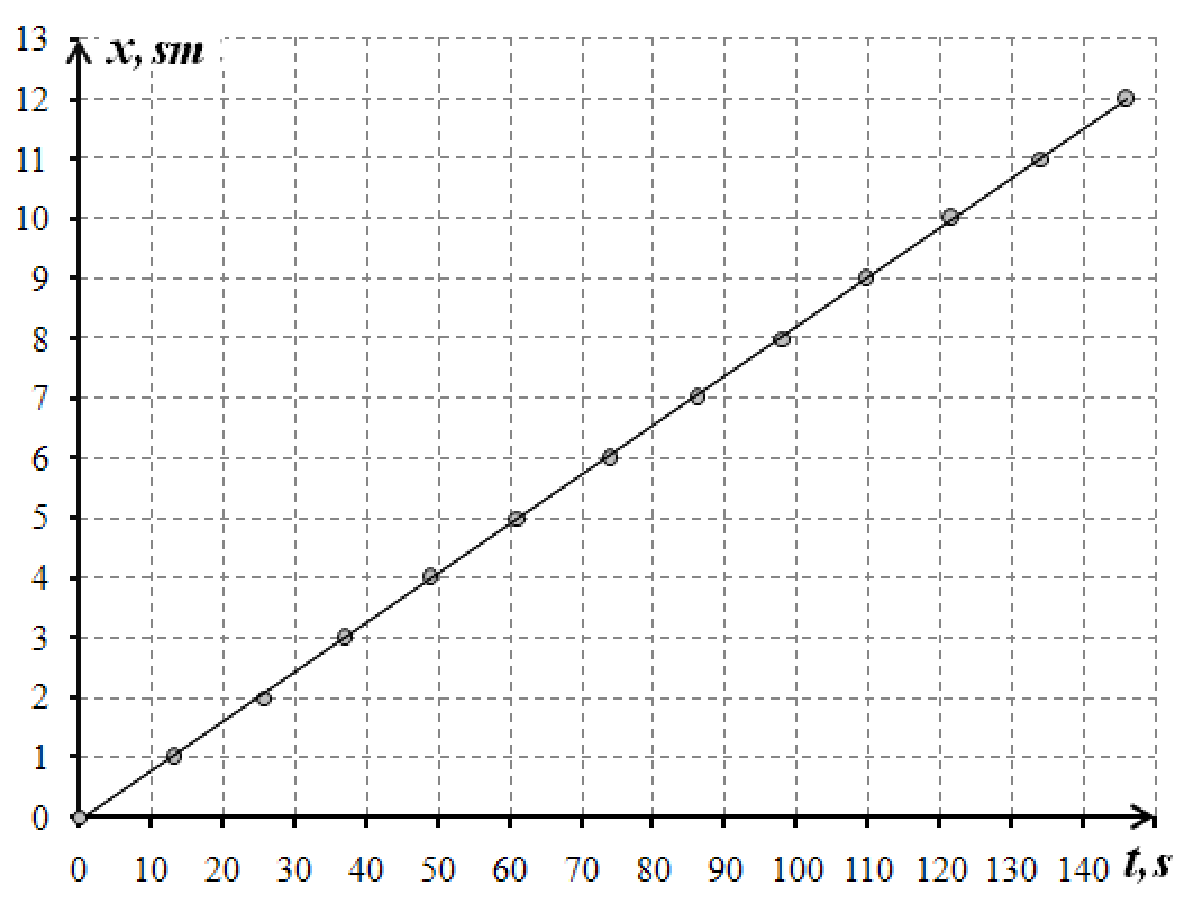
Table 3.
| x, см | t, c |
|---|---|
| 0 | 0,0 |
| 1 | 13,1 |
| 2 | 25,6 |
| 3 | 37,0 |
| 4 | 48,8 |
| 5 | 61,3 |
| 6 | 73,9 |
| 7 | 86,1 |
| 8 | 98,2 |
| 9 | 109,6 |
| 10 | 121,7 |
| 11 | 134,0 |
| 12 | 146,0 |
It is seen that the wood stick also emerges uniformly and its average velocity, calculated by the least-squares method from Table 3, is
- To obtain velocities it is enough to measure time intervals for a wood stick to pass a fixed path several times. Results of the measurements shows that within the experimental error the emerging velocity does not depend on the stick length and equals to
Thus, the plot is just a horizontal straight line.
- In this case the diameters of sticks are all equal. It is obvious that the viscous friction is proportional to the stick length. . The mass and the pressure difference is also proportional to the length . Consequently, it follows from formula (6) that the velocity of the flowing liquid and, thus, the velocity of the stick does not depend on the length.
Оригинал в Архива: IZhO-2010-Exp_eng.pdf · официални решения: IZhO-2010-Exp_eng_sol.pdf